Marine Electromagnetic Navigation: Where It Works Best and What Limits Accuracy
Where marine electromagnetic navigation creates the most value
Marine electromagnetic navigation becomes most useful when satellite positioning is unreliable, obstructed, or intentionally disrupted.
That practical value is not only technical.
It directly affects route continuity, maneuvering confidence, and safety margins in busy or constrained waters.
For GNCS, this fits a broader logic.
Precision spatial perception matters in marine navigation just as physical containment protection matters in cabins and vehicle structures.
In both cases, performance depends on how systems behave under real operating stress, not only on nominal specifications.
Marine electromagnetic navigation is therefore best judged by scenario fit.
A harbor approach, an offshore support mission, and a coastal survey task may all use similar positioning architecture.
Their accuracy limits, however, rarely come from the same source.
Why the same system behaves differently across waters
The first mistake is treating marine electromagnetic navigation like a fixed-accuracy product.
In actual deployment, it acts more like a field-dependent sensing method.
Signal propagation changes with seawater conductivity, seabed composition, coastal infrastructure, vessel geometry, and onboard electronics.
A muddy estuary can behave very differently from a rocky shelf.
So can a container terminal packed with cranes compared with an open offshore corridor.
That is why marine electromagnetic navigation should be assessed with layered data.
GNSS denial risk is only one layer.
The full picture also includes local electromagnetic noise, expected maneuvering precision, installation constraints, and compliance requirements tied to navigation integrity.
Ports and terminal approaches often reward controlled coverage
Ports are among the strongest use cases for marine electromagnetic navigation.
The reason is not simply signal weakness.
Ports combine narrow maneuvering lanes, metal-heavy infrastructure, vessel congestion, and operational pressure during docking windows.
In these conditions, a resilient local positioning layer can support continuity when satellite readings drift or fluctuate.
What matters most here is coverage stability near fixed assets.
Crane arrays, high-voltage equipment, and dense communications traffic may distort readings more than open-water factors do.
A system that looks accurate in bench testing can lose practical value if berth-side interference was underestimated.
The better approach is to validate electromagnetic behavior along the full arrival path, not only at the berth.
Transition zones usually reveal the real weaknesses.
What to confirm before using it in port operations
- Field uniformity near quay walls, breakwaters, and steel structures.
- Interference exposure from radar, VHF, power systems, and terminal automation equipment.
- Position refresh behavior during low-speed turns and lateral berthing corrections.
- Integration quality with ECDIS, AIS, inertial sensors, and pilot assistance functions.
Offshore work benefits when continuity matters more than map-like precision
Offshore support, subsea inspection, and platform-adjacent operations present a different judgment pattern.
Here, marine electromagnetic navigation is often valued for continuity under disturbed satellite conditions.
Absolute accuracy still matters, but repeatable positioning can be even more important.
This is especially true when vessels hold relative position near assets, cables, or exclusion zones.
Compared with ports, offshore areas usually face less structural clutter.
The challenge shifts toward water depth, seabed conductivity variation, weather-driven motion, and equipment integration with dynamic positioning logic.
A common misjudgment is assuming open space automatically means better marine electromagnetic navigation accuracy.
In reality, deeper or geologically complex zones may weaken consistency if the signal model was tuned for shallower coastal environments.
That is why offshore deployment should include environmental remapping over time, not only an initial calibration campaign.
Coastal corridors and estuaries demand closer attention to local conditions
Coastal shipping lanes and estuarine passages are less predictable than they first appear.
Marine electromagnetic navigation can work very well there, yet accuracy limits often come from local variability.
Salinity changes, tidal movement, sediment transport, and shoreline infrastructure can alter signal behavior within relatively short distances.
This is where generic system claims become less useful.
The key question is not whether marine electromagnetic navigation works in coastal waters.
The better question is which coastal segment stays stable enough for the required operational tolerance.
Shallow dredged channels, ferry crossings, and river-mouth approaches each need a separate error picture.
In practical terms, these routes benefit from paired validation.
One layer checks baseline electromagnetic performance.
The other tracks how seasonal or tidal change shifts that baseline.
Different waters change the decision focus
A simple comparison helps clarify where marine electromagnetic navigation fits best.
This comparison also explains why GNCS tracks marine navigation with the same discipline used in safety-critical mobility systems.
Performance only becomes meaningful when measured against operational context.
Where accuracy usually degrades faster than expected
Several limits on marine electromagnetic navigation are regularly underestimated.
Seabed conductivity is one of them.
Teams often note it during design review, then fail to treat it as a live operational variable.
Electromagnetic interference is another.
Interference rarely comes from one dramatic source.
More often, several moderate sources combine into a navigation quality problem.
Installation quality also changes outcomes.
Cable routing, antenna or sensor placement, shielding choices, and vessel-specific metal geometry can alter measured performance enough to affect operational decisions.
Another weak point is overconfidence in one-time acceptance testing.
Marine electromagnetic navigation should be reviewed after route changes, terminal expansion, onboard retrofit work, or major software integration updates.
Common misreads in deployment planning
- Assuming similar coastlines produce similar signal behavior.
- Focusing on purchase specifications instead of field verification.
- Ignoring maintenance workload for recalibration and interference checks.
- Separating navigation performance from broader safety and compliance workflows.
A more reliable way to match marine electromagnetic navigation to the job
A useful selection process starts with the route, not the hardware brochure.
Define where continuity is essential, where tolerances tighten, and where environmental change is most likely.
Then examine how marine electromagnetic navigation will interact with existing navigation layers.
In many cases, the best result comes from integration, not replacement.
That means combining electromagnetic positioning with inertial references, sonar inputs, radar awareness, and chart-system logic.
It also means setting practical thresholds for degraded mode operation.
If a system remains usable within defined error bands, it can still deliver high operational value.
The final decision should include four checks.
- Map the exact waters where satellite instability creates operational risk.
- Test marine electromagnetic navigation against real interference and seabed conditions.
- Compare lifecycle effort, including calibration, updates, and integration maintenance.
- Build scenario-based acceptance criteria instead of one universal accuracy target.
That approach creates a clearer foundation for implementation, risk control, and long-term system confidence.
For organizations following GNCS, the next practical step is to sort operations by water type, interference exposure, and maneuvering precision, then validate marine electromagnetic navigation against those specific conditions.
Related News
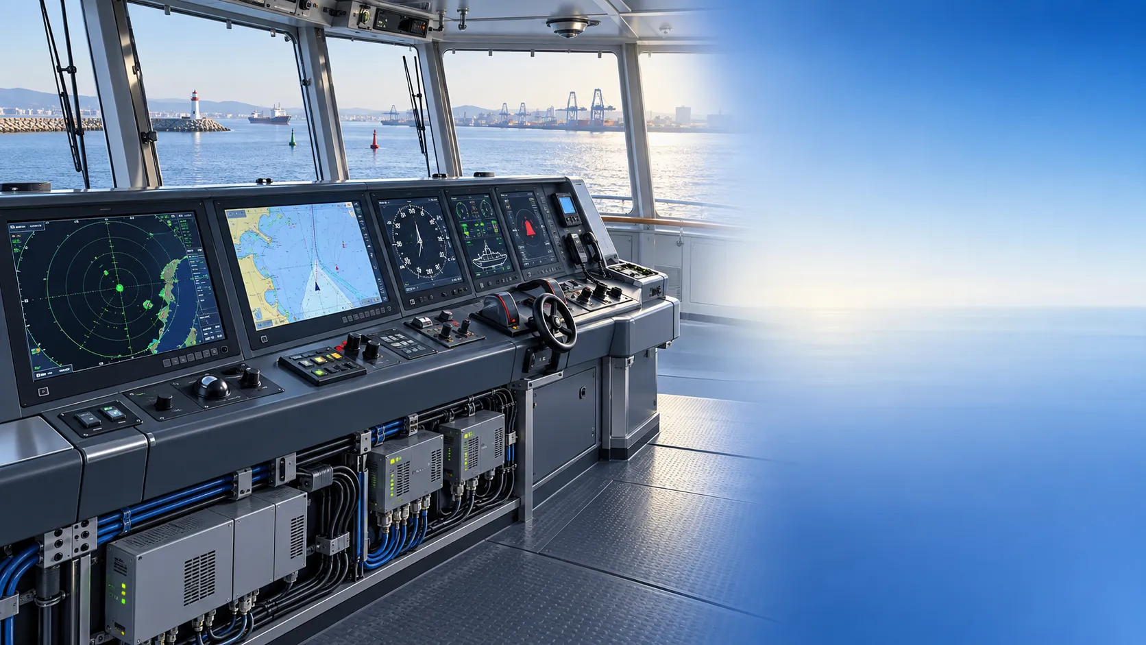
How to Specify Integrated Marine Electronics for Reliable Bridge Operations
Integrated marine electronics: learn how to specify reliable bridge systems with clear data flows, redundancy, alarm control, lifecycle interfaces, and operational testing.
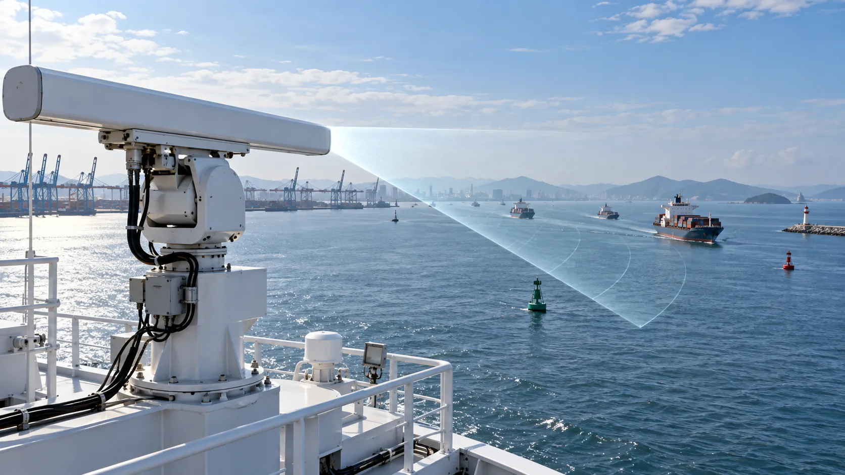
How to Evaluate Navigation Radar Manufacturers for Commercial Vessel Projects
Navigation radar manufacturers: learn how to compare performance, compliance, integration, support, and lifecycle cost for commercial vessel projects.

How Adjustable Cabin Ergonomics Reduce Operator Fatigue in Long-Shift Vehicles
Adjustable cabin ergonomics reduces operator fatigue through better seating, reach, visibility, vibration control, and climate comfort for safer long-shift vehicles.

How Rear-Impact Safety Components Work Together to Protect Vehicle Occupants
Explore how automotive safety components for rear impact work together—from crash structures and seats to head restraints and belts—to enhance occupant protection.
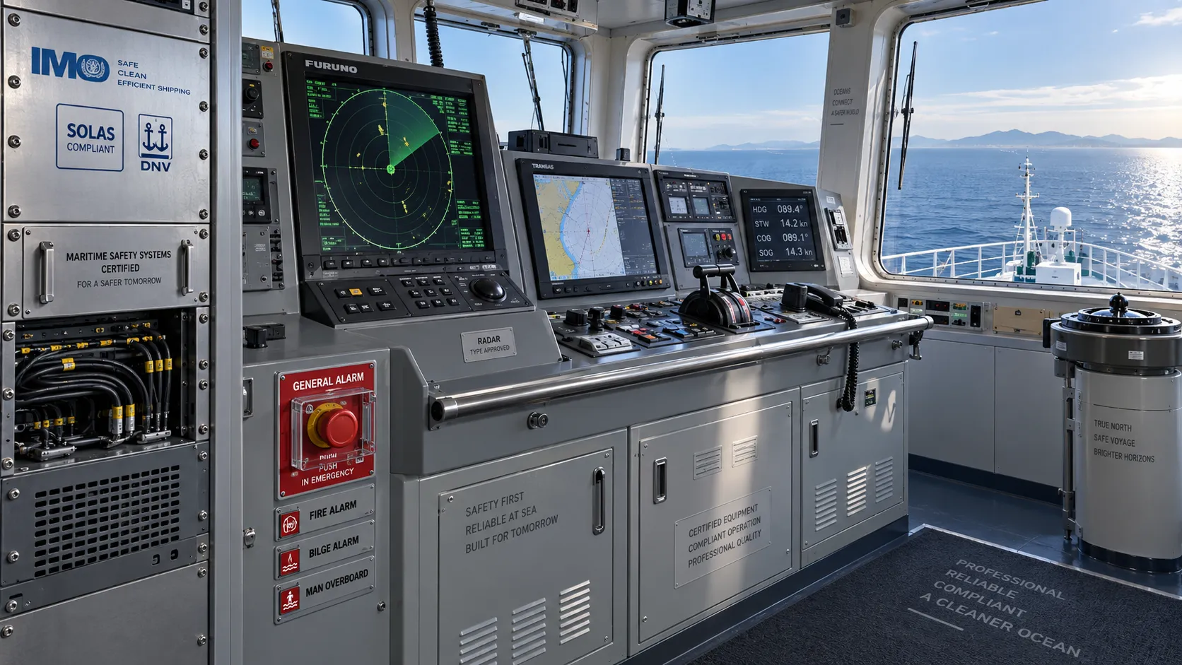
How to Evaluate a Marine Safety Systems Manufacturer for Vessel Compliance and Reliability
Marine safety systems manufacturer evaluation guide: verify compliance, engineering quality, lifecycle costs, and global service support for safer, reliable vessel operations.

Crash Test Regulations for Seatbelts: Key Compliance Requirements Explained
Crash test regulations seatbelts explained: explore FMVSS, UN rules, anchorage strength, and dynamic restraint testing for safer, compliant vehicle systems.

How to Calculate the Total Cost of Automotive Lightweighting for a Vehicle Program
Automotive lightweight solutions cost: learn how to calculate program-level costs, including materials, tooling, joining, validation, risk, and vehicle-level value.

How Automotive Seat Occupancy Sensing Improves Airbag Deployment Decisions
Automotive seat occupancy sensing helps optimize airbag deployment decisions, improving passenger classification, safety diagnostics, and compliance across real-world conditions.

What Drives Lightweight Body Component Costs in High-Volume Vehicle Programs?
Lightweight body components cost depends on material yield, forming, joining, tooling, validation, and logistics. Explore proven ways to optimize total vehicle program cost.
Related News
- 00
0000-00
How to Choose a Marine Positioning Solutions Supplier in Europe for Offshore and Port Operations - 00
0000-00
Marine Positioning Solutions Provider Comparison: GNSS, Accuracy, and Integration Factors - 00
0000-00
Marine Electromagnetic Navigation Accuracy vs GNSS: Which Performs Better Near Interference? - 00
0000-00
Marine Electromagnetic Navigation Accuracy: What Affects Position Stability at Sea? - 00
0000-00
Marine Positioning Systems Exporter Selection: What to Check in GNSS Accuracy, Compliance, and Support
Weekly Insights
Stay ahead with our curated technology reports delivered every Monday.