
Compact Pretensioner Systems: Evaluating Packaging, Stroke, and Belt-Tightening Force
Compact Pretensioner Systems: Evaluating Packaging, Stroke, and Belt-Tightening Force
Smaller restraint components can simplify cabin integration, but reduced size alone does not establish safety performance. Compact pretensioner systems demand a careful assessment of packaging constraints, usable stroke, and belt-tightening force under representative installation conditions. How effectively does actuator travel translate into webbing take-up, and how do mounting geometry, activation timing, and load-limiter coordination affect occupant restraint? These engineering relationships determine whether a space-saving design is suitable for a particular vehicle.
The selection problem is not simply finding the smallest unit that fits. It is finding a restraint architecture that removes the required slack, within the available time, without compromising belt positioning or subsequent energy management. A compact mechanism that performs well in a rigid test fixture may behave differently when attached to a compliant seat frame or routed through production trim.
Define the architecture before comparing dimensions
“Compact” is a packaging description, not a common performance class. A retractor pretensioner, buckle pretensioner, and outboard lap-anchor pretensioner act at different points in the belt system. Their dimensions, displacement figures, and output forces are therefore not directly interchangeable.
Retractor-based devices rotate the spool to retract webbing. Buckle devices pull the buckle assembly through a defined path, changing the geometry of both belt segments around the latch plate. Lap-anchor devices act at the outboard attachment to address lap-belt slack more directly. Combined arrangements may distribute tightening across several locations, but their interactions need evaluation rather than assuming that individual outputs simply add together.
Also distinguish crash-triggered, typically single-use pyrotechnic devices from reversible motorized belt-tightening functions. Reversible systems can manage slack before a predicted event, but they should not be treated as substitutes for crash pretensioners unless the complete architecture has demonstrated the required performance. Comparing these technologies solely by housing volume obscures their different operating duties.
Packaging includes the load path—not just the housing
An installation envelope must include connectors, harness bend requirements, fasteners, cable routing where applicable, assembly access, and clearance throughout seat adjustment. A smaller actuator may require a larger bracket or a less direct transmission path. The resulting installation can consume more usable space than its component drawing suggests.
Seat-mounted restraints make this particularly important. Seat height, fore-aft travel, recline, and buckle presentation can change the surrounding geometry. Check the full intended adjustment range, including tolerance combinations, rather than a single nominal seating position. Where cables or guides are used, their installed curvature and contact conditions should match the evaluated configuration.
Structural compliance deserves equal attention. During activation, mounting brackets and adjacent structures react the pretensioner load. Their deformation can alter the actuator’s effective motion relative to the occupant. Lightweight seat structures and body attachments therefore need to be assessed as part of the restraint load path, not treated as fixed boundaries by default.
The useful packaging question is: what installed space and supporting structure are required to deliver the intended belt action? That is a more meaningful comparison than actuator volume alone.
Translate nominal stroke into usable belt take-up
Stroke is easy to quote and easy to misread. It may describe piston travel, cable displacement, buckle movement, spool rotation converted to webbing length, or measured belt retraction. Before comparing candidates, establish exactly what moves, where displacement is measured, and what resistance is applied during measurement.
Actuator travel is not automatically equal to slack removed around an occupant. Transmission geometry, belt routing, webbing elongation, structural deflection, and interface settling all affect the relationship. In a buckle system, for example, buckle movement changes the paths of the lap and shoulder segments; it cannot be interpreted as identical take-up in each segment. Latch-plate friction can further influence how tension redistributes.
For retractor systems, the relationship between spool rotation and webbing take-up depends partly on the effective winding radius. Webbing payout and build-up on the spool can therefore matter. Ask whether the quoted retraction represents the belt payout expected in the vehicle, rather than an unrelated reference condition.
A useful stroke assessment separates three quantities: available mechanism travel, motion delivered at the belt interface, and the resulting change in belt fit or slack. Loaded displacement histories help connect them. A maximum unloaded stroke alone does not show whether sufficient movement remains when the mechanism encounters realistic resistance.
Peak force is not a complete tightening specification
A high peak output can look persuasive on a comparison sheet. However, a brief force spike does not demonstrate sustained belt take-up, and an actuator output force is not necessarily the tension reaching the occupant-facing webbing. Measurement location and test configuration must accompany every force claim.
Request force-time and displacement-time traces from the same test, with the applied resistance or fixture characteristics documented. These reveal whether motion occurs early enough, whether output drops before the required displacement is achieved, and whether the mechanism reaches its travel limit. Where relevant, examine residual holding behavior and any reverse movement after initial tightening.
Force and stroke also trade against each other through the transmission. A geometry that increases displacement may reduce available force, subject to the mechanism and its losses. The force-displacement relationship is therefore more informative than two independently quoted maxima that may never occur together.
More tightening force is not inherently safer. The objective is appropriate restraint engagement and occupant kinematics, followed by controlled management of crash loading. Excessive or poorly distributed tightening can create undesirable belt interaction. The acceptable output must be established with the intended belt geometry, occupant conditions, and crash environment.
Timing and load limiting must be evaluated together
Pretensioning removes slack and establishes restraint engagement; load limiting subsequently permits controlled belt payout under defined loading conditions. These functions should support one another. Evaluating either in isolation can miss an unfavorable transition between initial tightening and occupant loading.
Separate the controller’s firing decision from the pretensioner’s mechanical response. Command timing, initiation delay, force rise, and completion of useful take-up are different events. Supplier response times are comparable only when they use the same reference point and endpoint. A time measured from electrical initiation cannot be directly compared with one measured from the start of a crash pulse.
System testing should examine how pretensioning affects occupant excursion, belt loading, and airbag interaction before and during load-limiter payout. Multiple pretensioners may also require coordinated activation strategies. There is no universally correct firing sequence or force level independent of the vehicle, crash pulse, seating geometry, and occupant characteristics.
Build a comparison around evidence quality
Before ranking compact pretensioner systems, create a common test-definition sheet. Otherwise, an apparent performance advantage may simply reflect a more favorable fixture, temperature, belt payout, or loading condition. At minimum, the comparison package should identify:
- Configuration: hardware revision, mounting orientation, bracket stiffness, belt routing, and transmission details.
- Initial conditions: belt payout, initial slack or preload, seat position, and relevant environmental conditioning.
- Measurement definitions: displacement reference points, force-sensor locations, time zero, sampling, and filtering.
- Repeatability: individual test results, sample quantities, variability, and any incomplete or abnormal activations.
- Post-activation state: remaining travel, retention behavior, interference, and damage affecting the load path.
Environmental and durability evidence should reflect the vehicle program’s requirements. Temperature exposure, vibration, corrosion, and aging can affect different elements of the assembly. Do not assume that a successful room-temperature activation establishes performance after conditioning, or that component testing covers every installation-specific effect.
Bench tests are valuable for characterizing mechanisms. Sled tests connect those characteristics to occupant response under controlled dynamic conditions. Vehicle-level validation addresses the broader installation and crash environment. Simulation can help explore variations, but its predictions depend on validated component behavior and appropriate model assumptions.
Separate regulatory relevance from a component claim
Applicable requirements depend on the destination market, vehicle category, and approval route. UN Regulation No. 16 and U.S. FMVSS No. 209 and No. 208 are examples of relevant regulatory references, with different scopes covering belt assemblies and occupant protection. Their current provisions and applicability require program-specific review; they are not interchangeable component performance labels.
Euro NCAP and IIHS assessments introduce separate consumer-rating considerations. A statement that a pretensioner “supports” a rating target is not evidence that the installed vehicle achieves it. Request the applicable protocol version, vehicle configuration, test conditions, and results behind any such claim.
This distinction reflects the cross-system perspective of Global Navigation & Cabin Safety (GNCS): passive safety intelligence is most useful when component mechanics are connected to seat structures, airbag integration, and market-specific requirements. Isolated specifications cannot establish cabin protection.
Make the shortlist conditional on installed performance
Reject candidates that cannot meet hard installation constraints across the required adjustment and tolerance ranges. Compare the remaining designs using loaded take-up, time-resolved output, and occupant-system evidence under matched conditions. Keep unverified supplier claims separate from demonstrated results rather than giving both equal weight in a scoring matrix.
Before design release, confirm production configuration control, traceability, change-notification arrangements, and availability of representative validation hardware. Changes to a cable route, bracket, connector, or transmission detail may require further assessment even when the commercial designation stays unchanged.
The strongest candidate is not necessarily the smallest or the one with the highest stated force. It is the design that delivers the required belt action in the intended installation, coordinates with subsequent restraint loading, and has evidence robust enough to support that conclusion. If the loaded stroke, measurement definitions, or timing references remain unclear, the next step is a targeted test—not a final selection.
Related News

How to Evaluate Supplier Solution References Before Signing a Contract
Evaluate supplier solution references with confidence. Learn how to verify technical evidence, identify delivery risks, and close gaps before signing a contract.
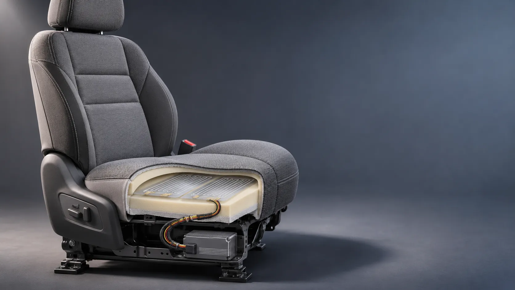
How Capacitive Seat Occupancy Sensing Works in Automotive Airbag Systems
Discover how capacitive seat occupancy sensing supports automotive airbag systems, and explore the design, calibration, and validation challenges behind reliable performance.
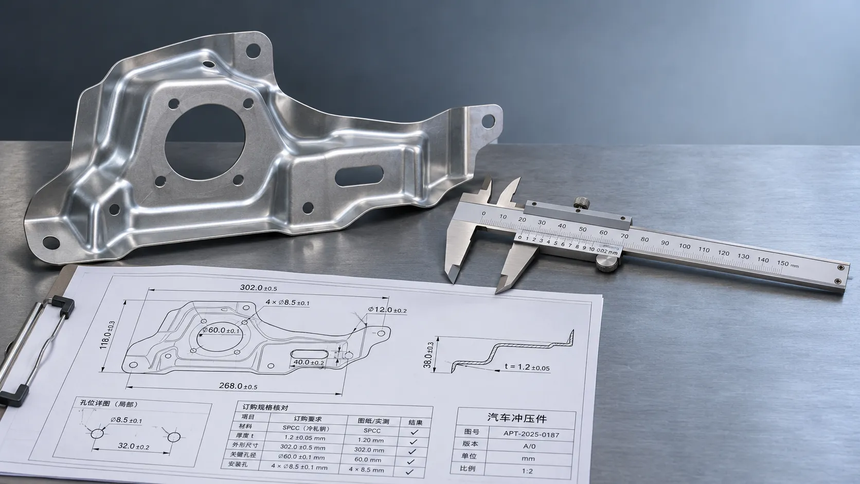
Industrial Product References: How to Verify Specs Before Ordering
Use an industrial product reference for procurement to verify specs, compatibility, and certifications before ordering—and reduce costly purchasing risks.
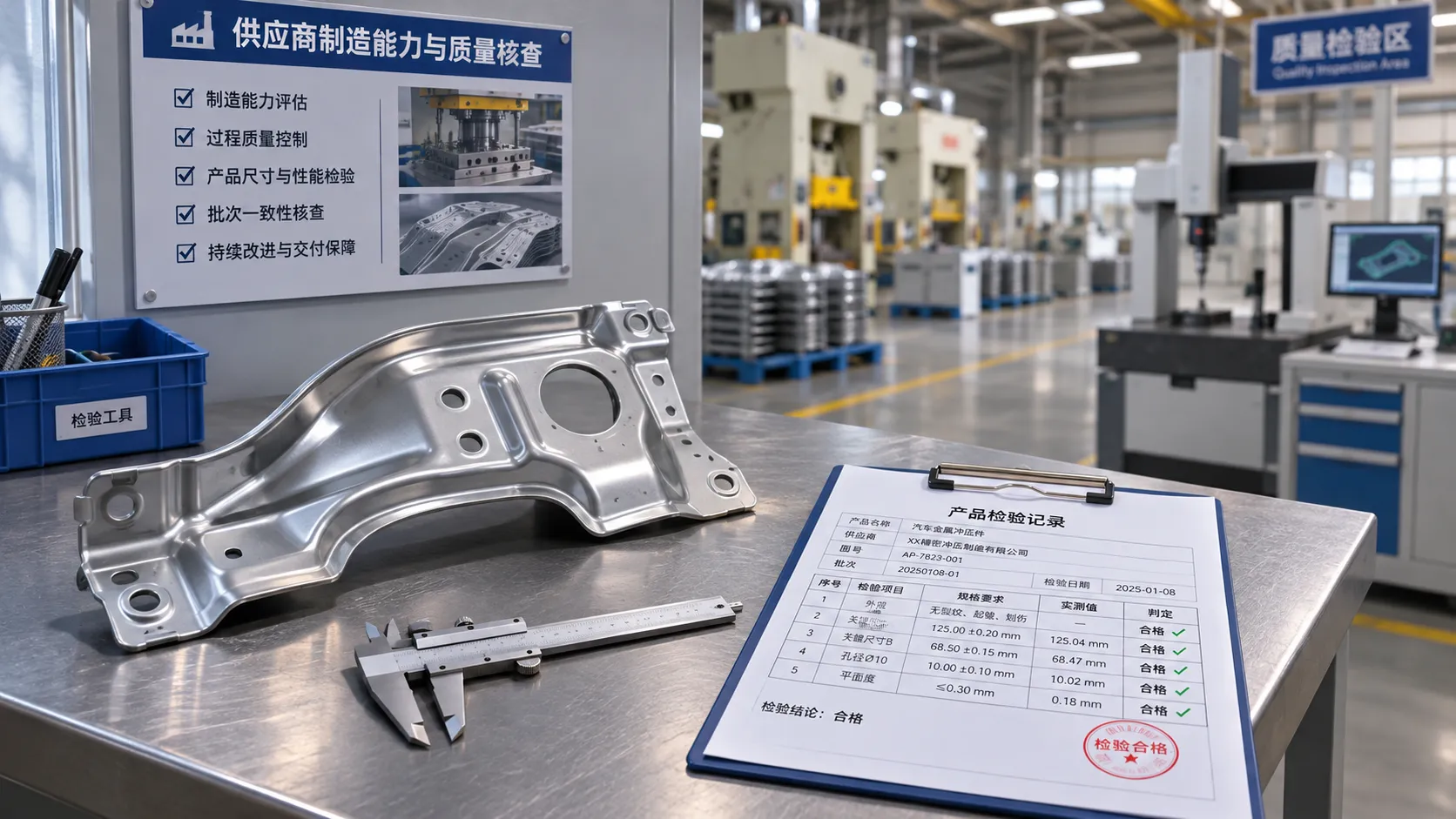
Choosing a Private Label Partner in Europe: Key Supplier Criteria
Private label cooperation Europe buyers can trust starts with the right supplier. Explore key criteria for compliance, quality, traceability and supply resilience.

Integrated Cabin Comfort Systems: How Seat and Cabin Climate Controls Work Together
Discover how integrated cabin comfort systems coordinate seat and climate controls to balance occupant comfort, energy use, safety, and performance.
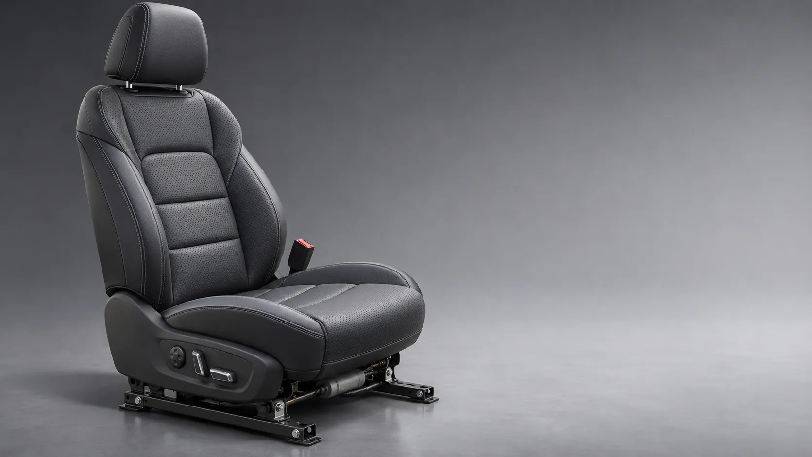
Automotive Ergonomics Pricing: What Drives Seat System Costs?
Discover what drives automotive ergonomics pricing, from seat mechanisms and safety systems to tooling and volume, and learn how to compare supplier quotes.

Evaluating Supplier Solutions: How to Verify References and Standards
Supplier solution references and standards can make or break a sourcing decision. Learn how to verify claims, assess compliance, and reduce risk before awarding a contract.
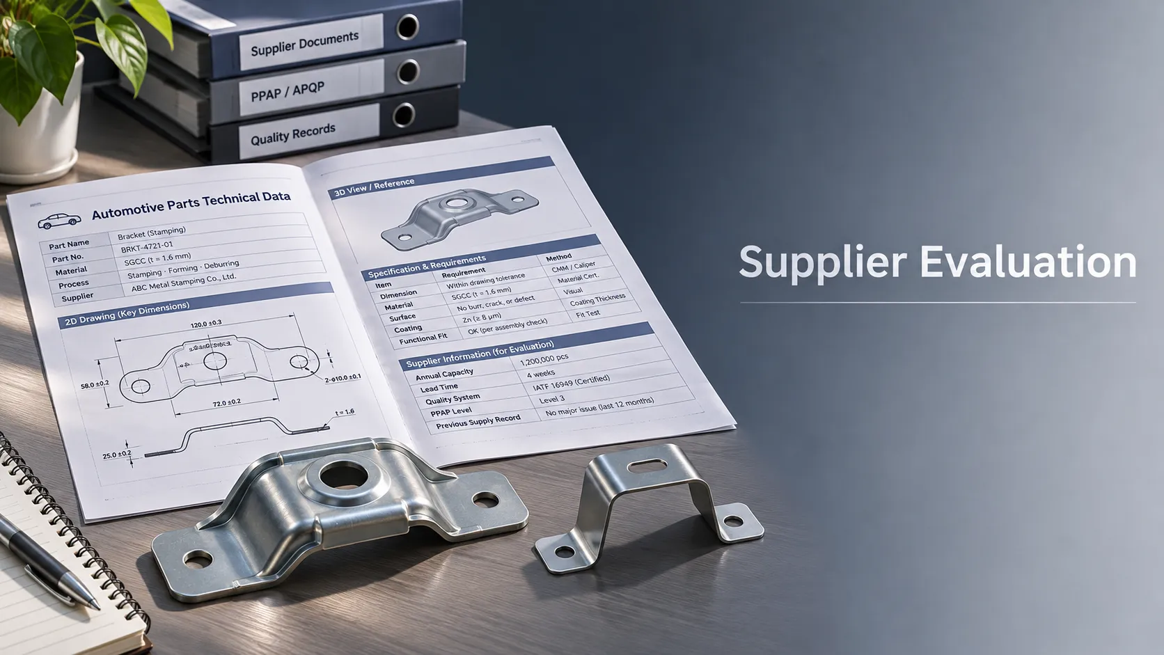
Choosing B2B Product Knowledge Platform Suppliers: Key Evaluation Criteria
Compare B2B product knowledge platform suppliers with confidence. Explore key criteria for data accuracy, supplier transparency, integrations, and value.
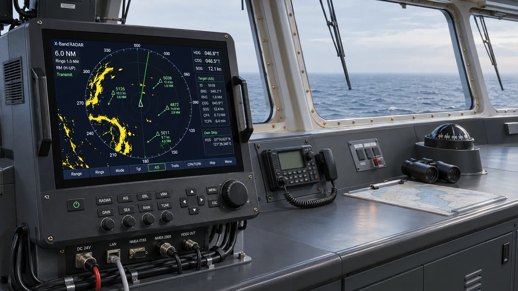
Choosing a Marine Radar Systems Supplier: What to Check Before Buying
Choosing a marine radar systems supplier? Compare installed costs, bridge compatibility, compliance evidence, and service support before you buy.
Related News
- 00
0000-00
Compact Pretensioner Systems: Evaluating Packaging, Stroke, and Belt-Tightening Force - 00
0000-00
How OEMs Evaluate Seatbelt Safety Systems for Vehicle Platform Integration - 00
0000-00
How Rear-Impact Safety Components Work Together to Protect Vehicle Occupants - 00
0000-00
Crash Test Regulations for Seatbelts: Key Compliance Requirements Explained - 00
0000-00
How Seat Belt Pretensioners for EVs Improve Crash Safety and System Response
0000-00
Weekly Insights
Stay ahead with our curated technology reports delivered every Monday.