
Skeletal Mechanics Structures Explained: Load Paths, Joint Behavior, and Design Limits
Skeletal Mechanics Structures Explained: Load Paths, Joint Behavior, and Design Limits
From shipboard equipment frames to automotive seat systems, skeletal mechanics structures shape how forces move through a product.
They do more than hold parts together.
They decide stiffness, energy absorption, vibration behavior, service life, and failure risk.
That is why skeletal mechanics structures matter across marine navigation hardware, lightweight auto bodies, passive safety modules, and smart seating platforms.
At a basic level, every structure answers three questions.
- Where does the load enter?
- How does it pass through members and joints?
- Where does deformation or failure start?
Once those answers are clear, design decisions become easier to defend.
This is especially true when cost, compliance, and lightweighting all push in different directions.
What Skeletal Mechanics Structures Really Mean
Skeletal mechanics structures are load-carrying frameworks made of beams, shells, tubes, brackets, rails, and connection points.
They are called skeletal because strength comes from the arrangement of members, not from solid mass alone.
A marine electronics rack is one example.
An automotive seat frame is another.
A body-in-white side structure also fits the same logic, even though geometry and materials look very different.
In practice, skeletal mechanics structures must balance local strength with global behavior.
A stiff bracket means little if the surrounding frame twists too easily or redirects load into a weak joint.
Understanding Load Paths
Load path is the most useful concept in skeletal mechanics structures.
It describes the route force takes from the point of application to the supports or restraints.
Good load paths are short, continuous, and predictable.
Poor load paths create detours, stress concentrations, and unstable deformation modes.
For example, in a seat frame during a rear impact, force moves through the recliner, side members, cross tubes, and floor mounts.
If one connection is too soft, the whole path changes.
That can increase occupant motion or overload nearby parts.
In marine equipment supports, repeated wave-induced vibration follows similar rules.
The frame must move loads into the vessel structure without amplifying resonance or loosening fasteners.
When engineers analyze skeletal mechanics structures, they usually check several load types together.
- Static loads from weight, preload, and mounting constraints
- Dynamic loads from vibration, shock, or crash pulses
- Thermal loads from expansion mismatch
- Fatigue loads from repeated use cycles
From a design review standpoint, the best question is simple: does the load path stay intelligible when real operating conditions stack together?
Why Joint Behavior Often Governs Performance
Most failures in skeletal mechanics structures do not begin in the middle of a clean member.
They begin at joints.
That includes welds, bolts, rivets, adhesives, hinges, recliners, tabs, and stamped intersections.
Joints matter because they are discontinuities.
Geometry changes there, stiffness changes there, and manufacturing variation usually appears there first.
A joint can behave as rigid, semi-rigid, or flexible.
That difference changes how moments and shear forces distribute across the structure.
In other words, joint behavior can completely rewrite the expected performance of skeletal mechanics structures.
Consider these common joint-driven issues:
- Bolt slip reducing initial stiffness
- Weld toe fatigue under cyclic bending
- Adhesive peel failure at edge zones
- Hinge backlash changing kinematics
- Heat-affected zones weakening high-strength steels
This is why testing only nominal material strength is not enough.
Real confidence comes from understanding connection behavior under assembly variation, wear, corrosion, and impact energy.
Design Limits: Where Performance Stops Being Reliable
Every structure has design limits, even when it looks overbuilt.
For skeletal mechanics structures, those limits usually appear in five forms.
- Yield limit, where permanent deformation begins
- Buckling limit, where thin members lose stability
- Fatigue limit, where cracks grow over repeated cycles
- Deflection limit, where stiffness becomes unacceptable
- Joint limit, where the connection fails before the member
These limits do not appear one at a time.
They interact.
A lightweight stamped member may pass static stress checks, yet fail buckling after a small geometric imperfection.
A seat back frame may survive peak crash load, yet exceed rotation limits that affect occupant protection performance.
A marine enclosure support may look strong enough, yet resonate under engine frequency and lose long-term reliability.
So, design limits are not only about breaking strength. They are about useful, repeatable, regulation-ready behavior.
Materials Change the Rules, but Not the Logic
The material choice strongly affects skeletal mechanics structures, especially under lightweighting pressure.
High-strength steel, aluminum, magnesium, and composites each shift the tradeoff between mass, stiffness, cost, and joining complexity.
Still, the core questions stay the same.
How will the load travel?
How will the joint respond?
Where is the first credible limit?
For example, aluminum can reduce mass well, but it often needs larger sections to recover stiffness.
Magnesium helps with aggressive weight targets, but corrosion control and joint design become more demanding.
Advanced steels support strong energy management, but forming limits and weld quality remain critical.
That is why material substitution alone rarely fixes a weak structural concept.
How Engineers Evaluate Skeletal Mechanics Structures
In current development programs, evaluation usually combines simulation, test data, and manufacturing feedback.
Finite element analysis is central, but it only works when assumptions match the real joint and boundary conditions.
A practical workflow often looks like this:
- Map the primary and secondary load paths
- Identify joints with stiffness uncertainty
- Screen for buckling, fatigue, and local stress peaks
- Correlate models with sub-system tests
- Update geometry and joining details before tooling freeze
This matters even more when standards compliance is involved.
Crash regulations, vibration standards, seat anchorage requirements, and marine equipment rules all reward predictable structural behavior.
The stronger signal in recent programs is clear: skeletal mechanics structures now need to satisfy both physical performance and traceable engineering logic.
Common Failure Patterns Worth Watching
Across sectors, several patterns appear again and again.
In real projects, recognizing these patterns early saves far more time than late-stage reinforcement.
What Good Structural Decisions Look Like
Good skeletal mechanics structures are not simply stronger.
They are clearer.
Their load paths make sense, their joints behave consistently, and their design limits are visible before production release.
This also means fewer surprises when regulations tighten or usage conditions shift.
For information tracking and technical benchmarking, the most useful habit is to read structures as systems, not isolated parts.
Ask where force enters, where it turns, where it concentrates, and where tolerance variation can break assumptions.
That approach makes skeletal mechanics structures easier to compare across marine, cabin safety, and lightweight mobility applications.
And it creates a better basis for judging durability, compliance readiness, and design maturity.
When the structural logic is sound, performance claims become much more credible.
Related News

Industrial Sourcing Information: How Buyers Vet Suppliers, Costs, and Supply Risks
Industrial sourcing information guide for vetting suppliers, calculating landed costs, managing compliance, and reducing supply-chain risks in marine and automotive safety programs.

Which Passive Safety Engineering Standards Apply to Automotive Restraint Systems?
Passive safety engineering standards for automotive restraint systems: explore FMVSS, UN regulations, seatbelts, airbags, anchors, and compliance planning.

How European B2B Teams Can Evaluate Product Intelligence Platforms for Sourcing
B2B product intelligence platform Europe: learn how procurement teams assess suppliers, compliance data, technical capabilities, and sourcing risks with confidence.

How to Evaluate Magnesium Alloys Corrosion Resistance for Marine Parts?
Magnesium alloys corrosion resistance for marine parts depends on more than alloy grade. Learn how to assess coatings, galvanic risk, geometry, and real-world exposure before you decide.

How to Evaluate Mobility Safety Systems for Safer Vehicle Platform Design
Mobility safety systems evaluation starts with platform architecture, crash energy management, and seat-restraint timing. Learn how to choose safer, validation-ready vehicle designs.

How Seat Belt Pretensioners for EVs Improve Crash Safety and System Response
Seat belt pretensioners for EVs improve crash timing, occupant control, and system response. Discover how smarter integration boosts EV safety performance.
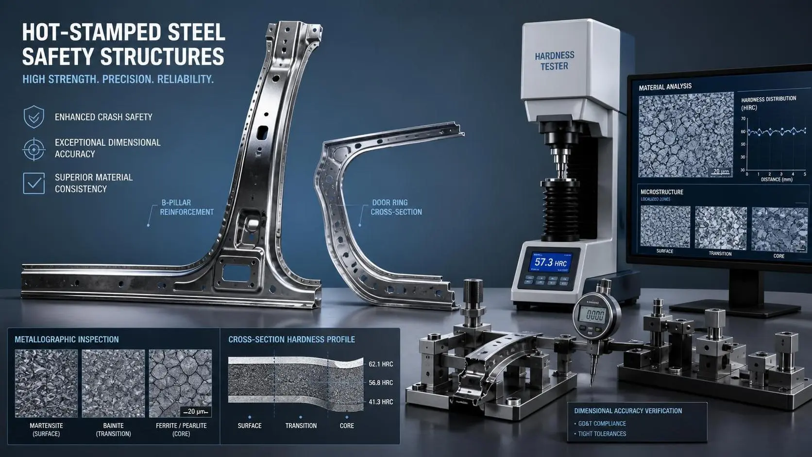
How to Evaluate High Strength Hot Stamped Steel Parts for Crash-Safety Applications
High strength hot stamped steel parts for crash-safety applications: learn how to assess strength, microstructure, dimensional accuracy, and process stability for safer sourcing decisions.
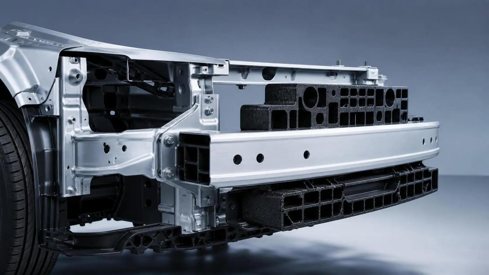
How Crash Management Components Reduce Repair Costs and Improve Impact Performance
Crash management components help reduce repair costs, protect critical vehicle structures, and improve impact performance. Learn how smarter design supports safer, more cost-efficient mobility programs.
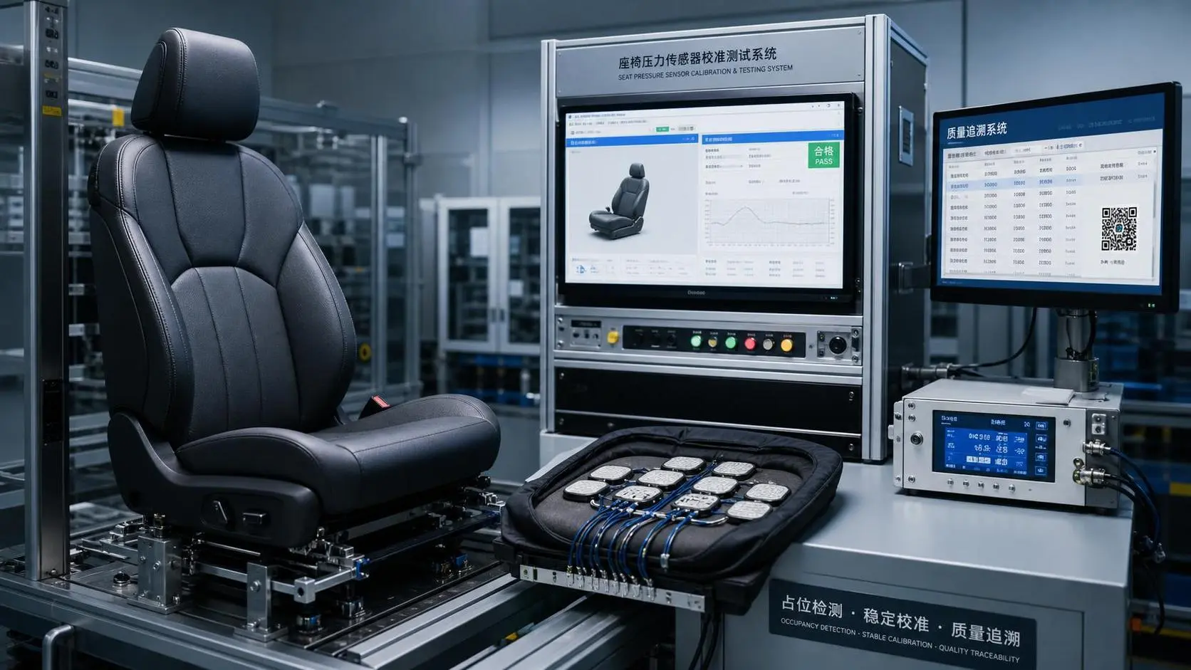
How to Evaluate a Seat Sensing Systems Factory for Automotive Safety Programs
Seat sensing systems factory selection goes beyond price. Learn how to assess quality control, validation, PPAP readiness, and long-term supply reliability for safer automotive programs.
Related News
- 00
0000-00
Industrial Sourcing Information: How Buyers Vet Suppliers, Costs, and Supply Risks - 00
0000-00
How European B2B Teams Can Evaluate Product Intelligence Platforms for Sourcing - 00
0000-00
How to Evaluate Magnesium Alloys Corrosion Resistance for Marine Parts? - 00
0000-00
How to Evaluate Mobility Safety Systems for Safer Vehicle Platform Design - 00
0000-00
How Crash Management Components Reduce Repair Costs and Improve Impact Performance
Weekly Insights
Stay ahead with our curated technology reports delivered every Monday.