
What Causes Seat Frame Failures in Crash Testing?
A seat frame failure in crash testing is rarely caused by one weak part alone. It is usually the visible result of a load path that was underestimated, a joint whose real production capability differs from its design assumption, or an interaction between the seat, belt, airbag, and occupant that concentrates force where the structure has little reserve.
The frame is not simply a support for cushions and adjustment mechanisms. In a frontal impact, it may transmit belt loads into the floor; in a rear impact, it must manage torso loading and head-restraint geometry; in side loading or oblique impact, it must preserve occupant position while resisting asymmetric deformation. A seat can remain visually intact yet fail its safety function if it rotates excessively, loses recliner lock integrity, permits belt geometry to collapse, or deforms enough to compromise restraint timing.
What counts as a seat-frame failure?
Failure does not always mean a complete fracture. Crash engineers assess whether the seat system maintains its required function under the applicable test condition. Relevant failure modes include:
- fracture or tearing of a rail, cross-member, back frame, bracket, or reinforcement;
- permanent deformation that causes excessive seatback rotation or cushion displacement;
- recliner unlocking, tooth damage, pawl slip, or housing separation;
- seat-track separation, track opening, or locking-pin failure;
- weld cracking, nugget pullout, heat-affected-zone fracture, or adhesive bond separation;
- loosening or pull-through of bolts, floor attachments, and integrated belt anchorages;
- loss of head-restraint position or excessive seatback collapse in rear loading.
The important distinction is between local damage and system-level loss of function. A localized yielding zone can be intentional if it controls energy and preserves belt and occupant geometry. By contrast, a small crack at a recliner bracket can be critical if it triggers rapid seatback rotation under occupant loading.
Why insufficient material strength is only part of the problem
Low material strength can certainly lead to bending, tearing, or buckling, particularly in thin-gauge stamped sections and high-load brackets. But selecting a higher-strength steel does not automatically create a safer seat. A stronger material can reduce ductility, increase sensitivity to forming-induced damage, make weld performance more demanding, and shift the failure to a neighboring component.
Seat structures often combine stamped steel sections, tubes, castings, forged components, wire forms, and increasingly lightweight materials. Their behavior depends on more than nominal grade. Material thickness, yield behavior, work hardening, elongation, bendability, coating condition, corrosion allowance, and strain-rate response can all influence crash performance.
A common design error is to evaluate a component through static strength alone. Crash loads are dynamic and directional. A rail that appears adequate in a vertical laboratory load may buckle when longitudinal compression and lateral offset occur simultaneously. Likewise, a seatback side member can resist a direct pull test but fail at a pierced hole or formed corner when the recliner transmits a twisting load.
Material variation must also be considered at the production level. Coil properties within specification can still influence forming results, springback, local thinning, and weld fit-up. If a design has very little margin, normal variation in sheet thickness or mechanical properties can produce inconsistent crash outcomes across builds.
Weak welds and joints often reveal the real structural limitation
Many apparent frame failures begin at a joint rather than in the base material. Spot welds, laser welds, MIG/MAG welds, rivets, clinches, bolts, and structural adhesives each require a load path suited to their actual capability. A joint designed only for nominal shear may be exposed to peel, cross-tension, prying, or combined loading during a crash.
Spot-welded flanges are especially sensitive to geometry. When a thin bracket opens under bending, the welds can see peel loading that is far more severe than the simplified shear load used in an early calculation. Weld nugget size, electrode condition, coating, stack-up, weld spacing, flange width, and access for welding all affect repeatability. A structurally sound computer model can therefore be undermined by a joint design that cannot be manufactured consistently at line speed.
Heat-affected zones deserve equal attention. High-strength steels may lose local properties after welding, while formed components may already contain residual strain near the joining area. Cracks can then initiate beside the weld rather than through it. In mixed-material structures, galvanic corrosion protection, adhesive cure conditions, thermal expansion mismatch, and mechanical fastening sequence can also influence long-term joint integrity.
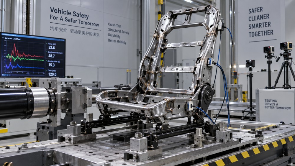
Joint validation should not stop at coupon testing. Coupons establish useful material and joint data, but they do not reproduce the rotation, fixture compliance, eccentricity, and multi-axis load transfer of a complete seat. Component-level tests, production-representative assemblies, and full-system crash correlation are needed to determine whether the joint remains robust when tolerances accumulate.
How poor load paths create failures even in strong frames
A crash load must travel from the occupant and restraint system through the seat, tracks, mounts, and vehicle body without generating uncontrolled local deformation. When that path contains abrupt section changes, unsupported spans, eccentric attachments, or highly flexible interfaces, force concentrates at a few locations.
Integrated seatbelt designs make this issue more acute. If the shoulder-belt upper anchorage or buckle load is carried by the seat, the frame must manage forces that a body-mounted belt system transfers directly into the vehicle structure. The seatback, recliner, cushion frame, tracks, and floor mounts become part of the restraint load path. Strengthening only the visible belt bracket may merely transfer the problem to the recliner pivot or track mounting area.
Load-path failures are frequently associated with:
- thin brackets attached to much stiffer members;
- large offsets between a load point and the member’s neutral axis;
- open sections that twist before they can develop bending capacity;
- holes, slots, and adjustment features placed in high-stress regions;
- abrupt thickness transitions without sufficient reinforcement or radius control;
- attachments that rely on fastener clamp load where direct bearing or positive engagement is needed.
The remedy is not always added mass. Reorienting a flange, moving a weld line, closing a section, adding a local load-spreading feature, or reducing eccentricity may be more effective than increasing gauge throughout the frame. Lightweight seat development depends on this distinction: mass removed from a low-stress area can be less consequential than a small geometric improvement at a critical force transfer point.
Why recliners, tracks, and locking mechanisms are recurring risk areas
Seats contain moving mechanisms, and every adjustment function introduces clearances, interfaces, and potential load discontinuities. Recliners must resist torque from the occupant’s upper body while maintaining the intended seatback angle. A mechanism can fail through tooth deformation, pawl disengagement, housing distortion, shaft fracture, or inadequate synchronization between left and right sides.
Asymmetry matters. In an offset frontal impact or an oblique loading condition, one side of the seat can carry substantially more load than the other. If the two recliners do not share torque predictably, the seatback may twist. This can alter shoulder-belt routing, increase occupant excursion, or overload a side frame member that was not designed as the primary load carrier.
Tracks face a related challenge. Their locking features must remain engaged under fore-aft loading, but the track pair must also tolerate racking. Slight differences in mounting height, rail parallelism, latch engagement, or floor-pan stiffness can cause one track to attract load earlier. A test article may then fail at a track or mounting bolt even though the nominal frame design appears adequate.
How restraint-system interaction changes the loading picture
The seat does not experience a crash independently of the occupant restraint system. Belt pretensioning reduces slack and changes the timing of load transfer. Force limiters affect the load delivered through the shoulder belt. Airbags influence occupant motion, while seat cushions and anti-submarining features influence pelvis position. Each feature can change where, when, and how the frame is loaded.
For example, a seat frame may pass a test with a body-mounted belt but show excessive deformation when equipped with an integrated belt system. A change in belt anchorage height can alter the moment acting on the seatback. A cushion that allows excessive compression or forward pelvis movement can change lap-belt loading and increase forces near buckle anchorage structures. Occupant size, seating position, recline angle, and seat fore-aft setting are also relevant because they alter both restraint geometry and structural leverage.
This is why seat-frame validation cannot rely on a single crash pulse or one occupant representation. The critical configuration may not be the nominal driving position. A tall occupant, a rearward seat position, an adjusted recliner angle, or an out-of-position setup may expose a different failure mode. Engineering teams need to identify the configurations that create peak force, peak moment, maximum rotation, and worst-case joint loading rather than assuming they occur together.
Can simulation miss a crash failure?
Yes. Finite element analysis is indispensable for modern seat development, but its predictive value depends on inputs that are often difficult to characterize. Material cards must capture relevant strain-rate behavior and failure limits. Weld models must represent failure mode, not merely stiffness. Contacts, bolts, recliner mechanisms, foam, trims, and tolerance-driven gaps can affect timing and load redistribution.
The most damaging simulation errors are often not numerical; they are modeling assumptions. Treating a joint as rigid can hide flange opening. Using idealized mount stiffness can conceal vehicle-body compliance. Omitting manufacturing variation can produce a design that passes virtually but has weak production robustness. A model calibrated only against one loading direction may not predict an oblique or asymmetric event.
Correlation should therefore focus on the mechanisms that govern failure: displacement history, rotation, force paths, local deformation, joint opening, and timing of lock engagement or separation. Matching one peak acceleration trace is not enough if the model reaches that peak through the wrong structural behavior.
Manufacturing defects and tolerance stack-up can turn marginal designs into failures
Crash performance is strongly affected by build quality. Mislocated welds, incomplete weld penetration, damaged electrodes, inconsistent adhesive application, missing fasteners, incorrect torque, distorted stampings, and poor rail alignment can all reduce performance. Not every defect produces an immediate failure; some introduce eccentricity that becomes significant only under dynamic load.
Tolerance stack-up is particularly important around tracks, recliners, belt brackets, and floor attachments. If the left and right sides of a seat do not engage simultaneously, one side may be loaded first and plastically deform before the intended load sharing begins. If a bolt-hole relationship allows excessive clearance, the assembly can shift before bearing load develops, altering the crash pulse seen by the frame.
Production control should connect critical-to-safety characteristics to the actual failure mechanisms. That means monitoring more than general dimensional conformance. Where weld location, nugget quality, fastener torque, recliner engagement, or bracket geometry governs crash performance, those characteristics require traceable control plans and meaningful verification methods.
What standards and test requirements should be considered?
Applicable requirements depend on the market, vehicle category, seating position, and restraint architecture. In the United States, FMVSS No. 207 addresses seating systems, while FMVSS No. 210 addresses seat belt assembly anchorages. Where a seat incorporates restraint anchorages, the interaction between these requirements becomes particularly important. Other markets use UNECE regulations, including UN Regulation No. 17 for seats, their anchorages, and head restraints, with belt anchorage requirements addressed under other relevant UNECE provisions.
Consumer-information programs and vehicle assessment protocols can add demands beyond minimum regulatory compliance, particularly through full-vehicle frontal, side, rear, and oblique impact evaluations. Their procedures change over time, so a seat program should use the current protocol and confirm its applicability rather than treating a past test setup as a permanent benchmark.
Regulatory compliance is necessary but does not by itself demonstrate manufacturing robustness. A design near its allowable limit can pass a certification test while remaining vulnerable to material, process, or vehicle-interface variation. The more integrated the seat is with belts, airbags, occupant sensing, and powered adjustment systems, the more important system-level validation becomes.
The practical question is where the first irreversible weakness appears
When a seat frame fails in crash testing, the useful investigation is not “which part broke?” but “which load transfer became unstable first?” The visible fracture may be secondary. A torn weld can follow excessive bracket rotation; bracket rotation can follow track racking; track racking can originate in uneven floor-mount stiffness or an overlooked belt-induced moment.
A sound corrective action identifies that chain, tests it across relevant seat positions and restraint conditions, and confirms that the improvement does not move the failure into another component. Stronger steel, additional welds, or thicker brackets may be justified, but only when they address the governing mechanism. Crashworthy seating depends on a controlled structural system—not on isolated parts that appear strong in isolation.
Related News

How to Evaluate Supplier Solution References Before Signing a Contract
Evaluate supplier solution references with confidence. Learn how to verify technical evidence, identify delivery risks, and close gaps before signing a contract.
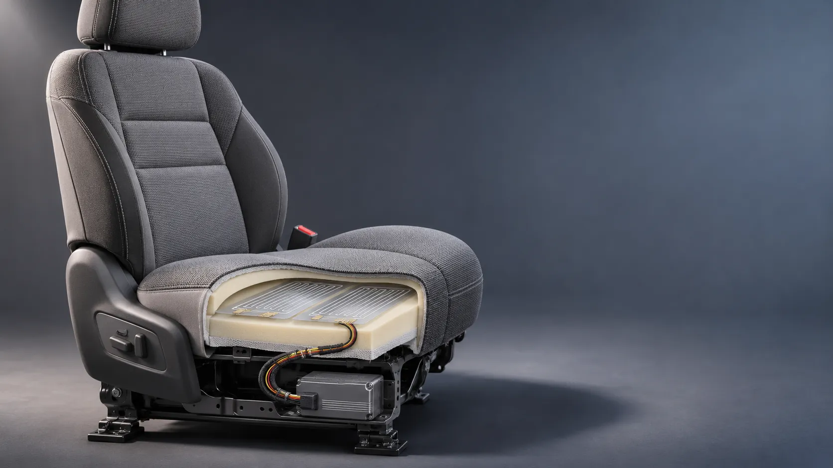
How Capacitive Seat Occupancy Sensing Works in Automotive Airbag Systems
Discover how capacitive seat occupancy sensing supports automotive airbag systems, and explore the design, calibration, and validation challenges behind reliable performance.
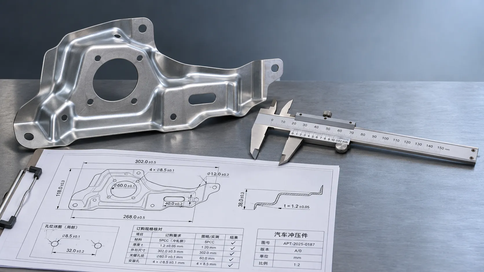
Industrial Product References: How to Verify Specs Before Ordering
Use an industrial product reference for procurement to verify specs, compatibility, and certifications before ordering—and reduce costly purchasing risks.
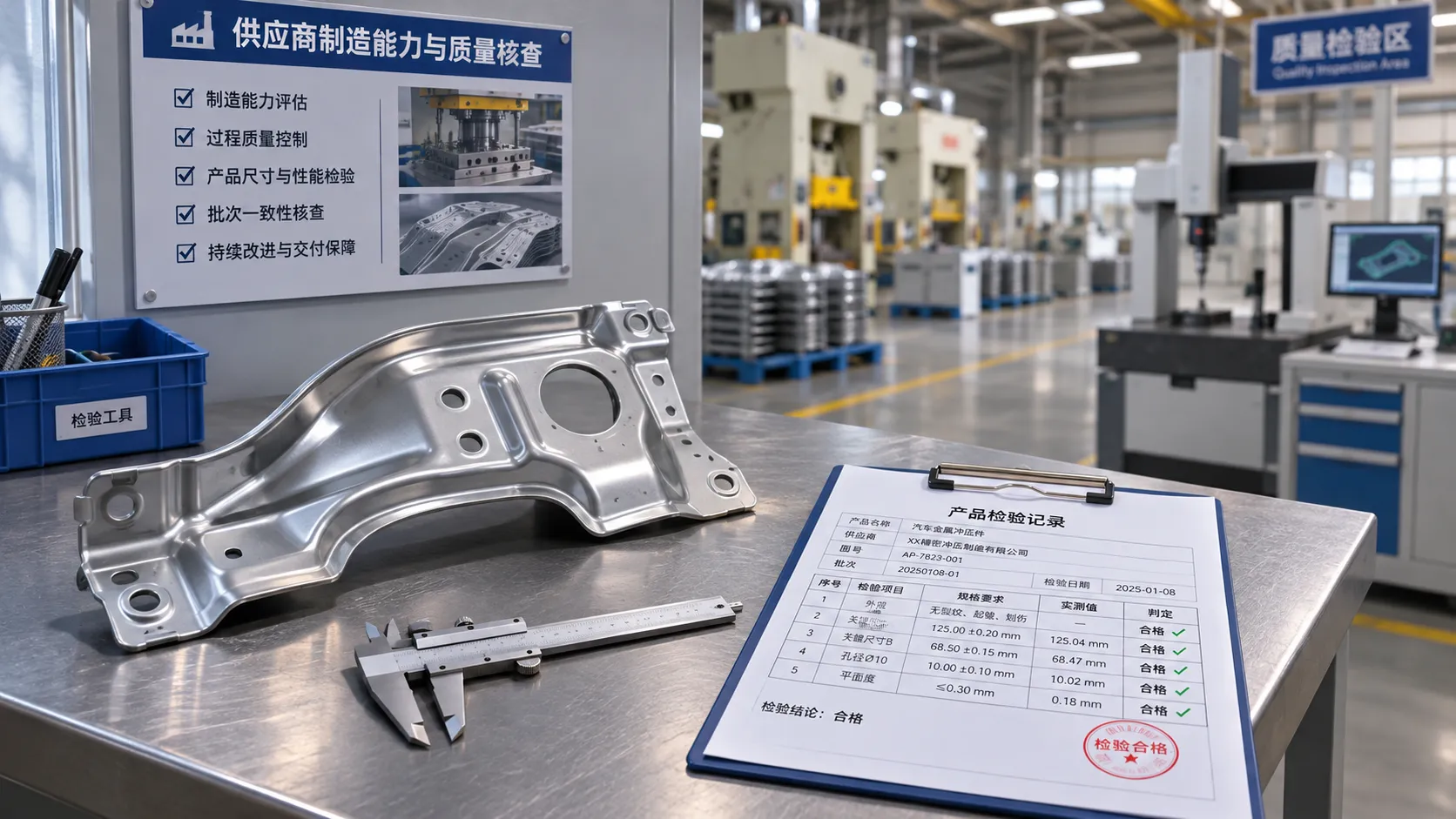
Choosing a Private Label Partner in Europe: Key Supplier Criteria
Private label cooperation Europe buyers can trust starts with the right supplier. Explore key criteria for compliance, quality, traceability and supply resilience.

Integrated Cabin Comfort Systems: How Seat and Cabin Climate Controls Work Together
Discover how integrated cabin comfort systems coordinate seat and climate controls to balance occupant comfort, energy use, safety, and performance.
Automotive Ergonomics Pricing: What Drives Seat System Costs?
Discover what drives automotive ergonomics pricing, from seat mechanisms and safety systems to tooling and volume, and learn how to compare supplier quotes.
Evaluating Supplier Solutions: How to Verify References and Standards
Supplier solution references and standards can make or break a sourcing decision. Learn how to verify claims, assess compliance, and reduce risk before awarding a contract.

Choosing B2B Product Knowledge Platform Suppliers: Key Evaluation Criteria
Compare B2B product knowledge platform suppliers with confidence. Explore key criteria for data accuracy, supplier transparency, integrations, and value.

Choosing a Marine Radar Systems Supplier: What to Check Before Buying
Choosing a marine radar systems supplier? Compare installed costs, bridge compatibility, compliance evidence, and service support before you buy.
Related News
- 00
0000-00
Seat Frame Components in Europe: How to Evaluate Suppliers and Quality - 00
0000-00
Adjustable Ergonomic Seat Frames: Evaluating Travel Range and Load Capacity - 00
0000-00
Are Magnesium Alloy Seat Frames Harder to Repair After a Crash? - 00
0000-00
What Causes Seat Frame Failures in Crash Testing? - 00
0000-00
How to Select Metal Automotive Seating Components for Strength, Weight, and Corrosion Resistance
0000-00
Weekly Insights
Stay ahead with our curated technology reports delivered every Monday.