
Adjustable Ergonomic Seat Frames: Evaluating Travel Range and Load Capacity
A seat frame’s adjustment range is useful only where it can maintain support, stiffness, and locking integrity under the required loads. A longer slide or greater lift does not automatically provide better ergonomic accommodation: extra travel may introduce positions with reduced rail overlap, higher bending moments, unfavorable linkage geometry, or interference with surrounding components.
The strongest basis for selecting adjustable ergonomic seat frames is therefore a verified operating envelope, not a pair of headline figures for travel and occupant mass. That envelope must connect each usable adjustment position to its load conditions, structural limits, adjustment performance, and durability evidence. For automotive applications, it must also remain compatible with the vehicle’s restraint system and applicable safety requirements.
Define usable travel at the occupant, not just at the mechanism
Fore-aft travel is frequently expressed as the distance between mechanical end stops. This describes the slide mechanism, but not necessarily the movement available after installation. Trim, wiring, floor geometry, control access, and surrounding structures can restrict the usable range. End-stop travel may also exceed the span over which every locking position is available.
Request separate values for mechanical stroke, lockable travel, and installed usable travel. For a manually adjusted rail, the distance between locking increments matters alongside total stroke. A generous range with coarse increments can leave an occupant unable to achieve the required pedal reach without compromising another aspect of posture.
Height adjustment requires similar scrutiny. A lifting mechanism can move the seat both vertically and longitudinally, while also changing cushion angle. Quoting the vertical displacement of one frame bracket does not establish the displacement of the occupant’s hip point.
The relevant geometry should be described through a consistent reference system:
- Fore-aft displacement relative to the vehicle or installation datums.
- Vertical movement of the seating reference point or measured occupant hip point under defined conditions.
- Cushion inclination and backrest angle throughout adjustment.
- Coupled movement between height, tilt, and longitudinal position.
- Clearance to pedals, steering controls, roof, console, and rear-seat space where applicable.
The design seating reference point and the measured H-point are related but not interchangeable. Their definitions, measurement procedures, and cushion-loading conditions must be consistent when comparing frames or complete seats. A bare-frame drawing cannot, by itself, establish occupant accommodation after foam, trim, and suspension elements are added.
Evaluate the adjustment envelope as a coupled system
Independent maximum values can create a misleading impression of flexibility. Maximum height, full rearward travel, and maximum recline may not be simultaneously available—or permissible—in an installed seat. The useful specification is a position map showing which combinations remain accessible, lockable, and structurally acceptable.
This matters because adjustment changes the load path. Raising the seat increases the distance between some applied loads and the floor attachments. Reclining the backrest changes the location and direction of loads transmitted through the recliner and seat base. Fore-aft movement alters rail engagement and the relationship between the upper structure and the mounting points.
Extreme positions deserve attention, but the worst condition is not necessarily an end stop. A height linkage can reach an intermediate geometry that produces high internal forces or low mechanical advantage. An actuator attachment may experience its highest force before maximum extension. The evaluation should use kinematic and structural analysis to identify critical positions, then validate those positions physically.
A practical comparison should distinguish the following:
Separate occupant mass from structural load capacity
A rating stated in kilograms is incomplete unless it identifies what mass is included and how the rating was established. Occupant mass, complete seat mass, supported accessories, and loads introduced through restraints may enter the structure through different paths. They should not be combined into one unexplained capacity figure.
For scale, a 120 kg mass produces approximately 1.18 kN of gravitational force under stationary conditions. This is an illustrative conversion, not a qualification load. Road inputs, abrupt vehicle motion, occupant movement, and collisions introduce different accelerations and force directions. Applying a single multiplier to body weight does not adequately represent all of them.
The load application point matters just as much as the force. A force acting farther from a support creates a larger moment. Consequently, a frame that carries a centered vertical load successfully may respond differently to an occupant sitting on the outer cushion edge, pushing against the backrest, or entering the seat while placing weight on one side.
Useful load documentation identifies:
- Force magnitude, direction, application area, and loading rate.
- Seat position, backrest angle, and adjustment-lock condition.
- Fixture stiffness, mounting geometry, and fastener specification.
- Whether the complete seat, frame assembly, or individual mechanism was tested.
- Permitted deflection, permanent set, slip, cracking, and loss of function.
Without these details, two identical capacity claims may describe substantially different performance. A component proof test and a complete-seat validation are not equivalent evidence.
Inspect the mechanisms that carry and retain the load
Rail section strength is only one part of longitudinal performance. Loads must pass through the upper and lower tracks, rolling or sliding interfaces, locking elements, brackets, welds, fasteners, and floor attachments. A strong rail profile cannot compensate for inadequate lock engagement or a flexible mounting bracket.
For paired manual tracks, verify that both sides achieve the intended engagement after adjustment. Release-linkage tolerances, assembly misalignment, and installation distortion can affect synchronization. A handle returning to its rest position does not, on its own, prove full engagement. The validation method should establish engagement directly or through a justified functional check.
Clearance and backlash also need separate acceptance criteria. Some movement originates in necessary running clearance; other movement may indicate wear, deformation, or incomplete engagement. Measure longitudinal, lateral, and rotational movement under defined loads rather than relying on an unloaded hand check.
Height mechanisms introduce additional considerations: pivot-bearing pressure, link bending, shaft torsion, gear loading, and attachment stiffness. Powered mechanisms must be assessed for lifting performance under the specified occupant load, not merely for holding capacity after adjustment. Motor current, temperature, adjustment speed, duty cycle, and stall protection can constrain usable operation even when the structure remains intact.
Retention after power loss must also be demonstrated where required. The presence of a screw drive or gearbox is not sufficient evidence of resistance to back-driving under every relevant load and wear condition.
Judge stiffness and fatigue separately from ultimate strength
A frame can avoid fracture yet still be unsuitable because it deflects excessively. Compliance can change posture, create movement relative to the controls, encourage contact with adjacent trim, or alter the geometry of seat-mounted restraint components. Service-load stiffness therefore needs its own limits rather than being inferred from a successful overload test.
Measure displacement at points that correspond to function: the cushion support, backrest top, recliner interface, and rail-to-floor attachments. Where useful, separate elastic movement from residual deformation after unloading. A single displacement reading can conceal which joint or subassembly is responsible.
Fatigue testing addresses a different question: whether repeated loading and adjustment degrade the frame over its intended service life. Relevant damage can develop at weld toes, holes, formed transitions, pivots, and fastener interfaces. Wear can also increase play or reduce locking quality without producing an obvious structural crack.
A meaningful durability program combines representative load histories with adjustment cycling and periodic functional measurements. Cycling an unloaded mechanism demonstrates movement endurance under that condition; it does not establish durability while supporting an occupant. Conversely, repeated vertical loading at one fixed position does not demonstrate adjustment-system life across the travel range.
Environmental conditioning should match the installation. Corrosion, temperature, contamination, and lubricant changes can affect sliding resistance and lock operation. The important result is not simply survival of exposure, but retained structural and functional performance afterward.
Keep crash evidence tied to the installation and restraint architecture
Automotive crash-related evaluation cannot be reduced to the frame’s maximum supported mass. Where restraint loads enter the seat changes the structural demand substantially. A seat with an integrated belt system transfers loads differently from one using vehicle-body belt anchorages. Even a seat-mounted buckle can introduce a significant additional load path.
Relevant regulatory frameworks include UN Regulation No. 17 for seats, their anchorages, and head restraints, and UN Regulation No. 14 for safety-belt anchorages within its applicable scope. In the United States, FMVSS No. 207 addresses seating systems, while FMVSS No. 210 addresses seat belt assembly anchorages. Exact applicability depends on the vehicle, seating arrangement, market, and current regulatory provisions.
These references are not interchangeable certifications for a generic frame. Evidence must identify the tested configuration, restraint attachments, seat position, mounting structure, and applicable requirements. A report covering one recliner, rail, or mounting arrangement does not automatically cover a modified assembly.
Nor does regulatory compliance alone establish satisfactory everyday stiffness, adjustment effort, or long-term wear. Those remain separate selection requirements. Crash strength, ergonomic accommodation, and service durability overlap through the same structure, but require distinct evidence.
Make selection conditional on a traceable performance envelope
The most useful supplier submission links drawings, mechanism versions, materials, joining specifications, and test reports to the exact proposed assembly. It should distinguish measured results from simulation and explain how critical adjustment positions were selected. Simulation is valuable for finding load concentrations and screening configurations, but its conclusions depend on realistic contact, joint, material, and boundary-condition assumptions.
Installation interfaces deserve particular attention. A frame tested on a rigid fixture may behave differently on a compliant floor or pedestal. Mounting flatness and fastener preload can affect rail alignment, operating effort, and load distribution. Acceptance should therefore include the intended support structure or a justified representation of its stiffness.
When comparing candidates, a shorter verified range can be preferable to a longer nominal range if both meet the required accommodation envelope. Conversely, reducing travel is not an acceptable substitute when it excludes required occupants or prevents correct control reach. The decision should follow the installed functional requirement, not an assumption that either maximum travel or maximum rigidity is inherently best.
The decisive evidence is a configuration-specific map of usable positions, load cases, deflection limits, locking performance, and durability results. Any range or capacity beyond that demonstrated envelope should remain outside the approved operating specification until supported by appropriate validation.
Related News

How to Evaluate Supplier Solution References Before Signing a Contract
Evaluate supplier solution references with confidence. Learn how to verify technical evidence, identify delivery risks, and close gaps before signing a contract.
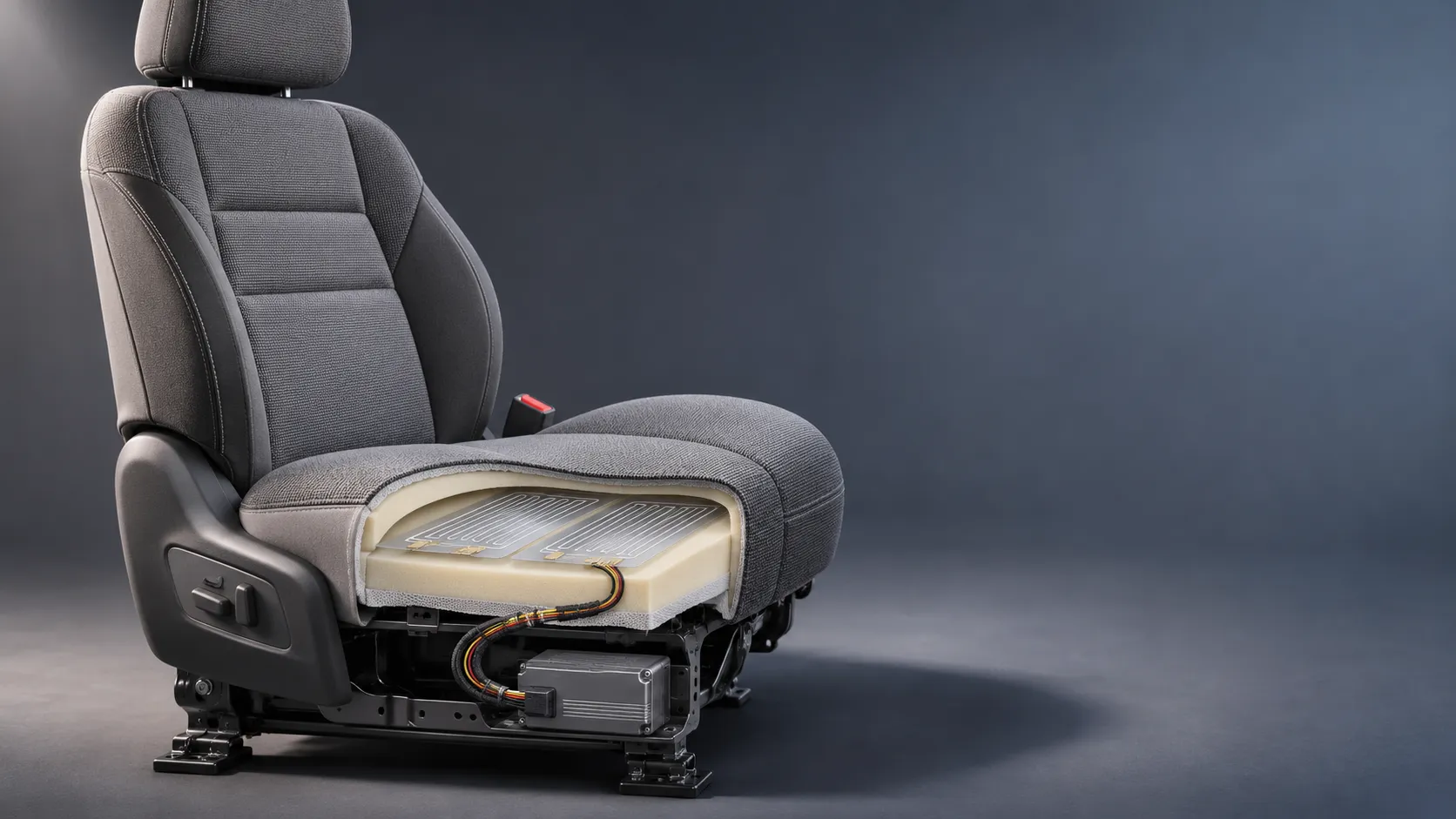
How Capacitive Seat Occupancy Sensing Works in Automotive Airbag Systems
Discover how capacitive seat occupancy sensing supports automotive airbag systems, and explore the design, calibration, and validation challenges behind reliable performance.
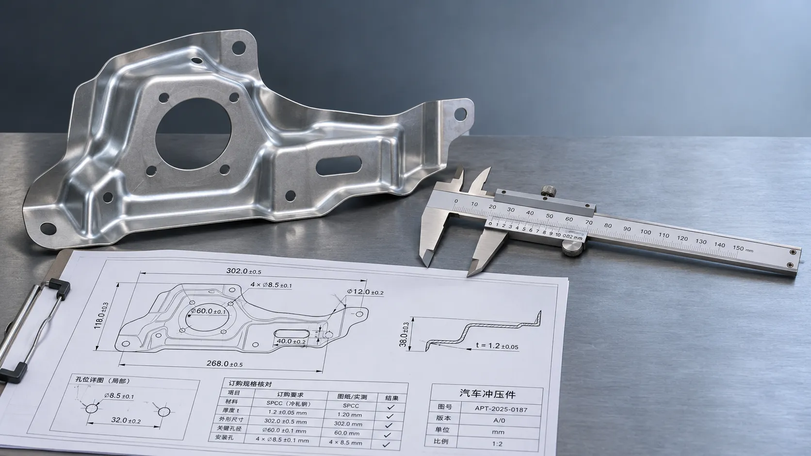
Industrial Product References: How to Verify Specs Before Ordering
Use an industrial product reference for procurement to verify specs, compatibility, and certifications before ordering—and reduce costly purchasing risks.

Choosing a Private Label Partner in Europe: Key Supplier Criteria
Private label cooperation Europe buyers can trust starts with the right supplier. Explore key criteria for compliance, quality, traceability and supply resilience.

Integrated Cabin Comfort Systems: How Seat and Cabin Climate Controls Work Together
Discover how integrated cabin comfort systems coordinate seat and climate controls to balance occupant comfort, energy use, safety, and performance.
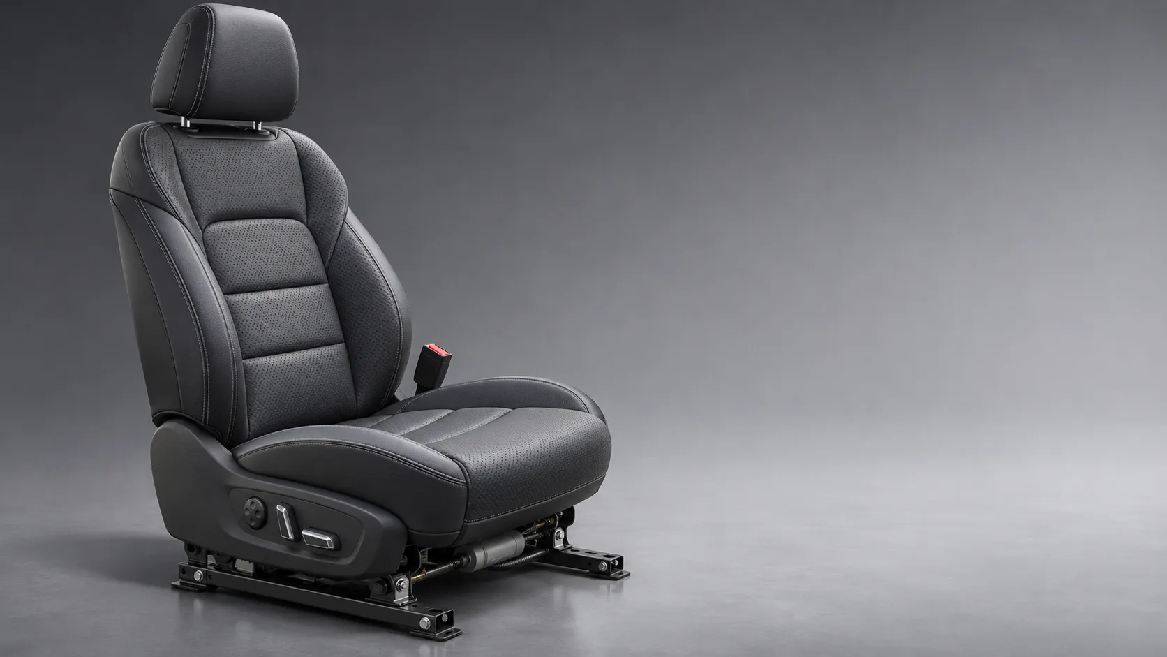
Automotive Ergonomics Pricing: What Drives Seat System Costs?
Discover what drives automotive ergonomics pricing, from seat mechanisms and safety systems to tooling and volume, and learn how to compare supplier quotes.
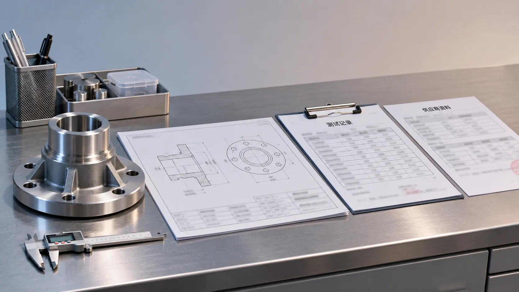
Evaluating Supplier Solutions: How to Verify References and Standards
Supplier solution references and standards can make or break a sourcing decision. Learn how to verify claims, assess compliance, and reduce risk before awarding a contract.

Choosing B2B Product Knowledge Platform Suppliers: Key Evaluation Criteria
Compare B2B product knowledge platform suppliers with confidence. Explore key criteria for data accuracy, supplier transparency, integrations, and value.

Choosing a Marine Radar Systems Supplier: What to Check Before Buying
Choosing a marine radar systems supplier? Compare installed costs, bridge compatibility, compliance evidence, and service support before you buy.
Related News
- 00
0000-00
Seat Frame Components in Europe: How to Evaluate Suppliers and Quality - 00
0000-00
Adjustable Ergonomic Seat Frames: Evaluating Travel Range and Load Capacity - 00
0000-00
Are Magnesium Alloy Seat Frames Harder to Repair After a Crash? - 00
0000-00
What Causes Seat Frame Failures in Crash Testing? - 00
0000-00
How to Select Metal Automotive Seating Components for Strength, Weight, and Corrosion Resistance
0000-00
Weekly Insights
Stay ahead with our curated technology reports delivered every Monday.