
How to Specify High-Strength Body Components for Crash Loads and Lightweighting
A body-in-white specification can fail even when every selected grade has an impressive tensile-strength value. The failure usually appears later: a rail tears at a trimmed edge, a tailor-welded blank distorts during forming, a spot-weld schedule becomes unstable, or a crash model shows an unintended hinge beside the intended crush zone. These issues affect both mass and safety because adding local reinforcement after tooling release often erodes the lightweighting target.
The practical answer is to specify high strength body components as a load-path and manufacturing system, not as isolated material callouts. Start with the crash function required at each location, translate it into measurable performance targets, then verify that the proposed material, thickness, geometry, joining method, coating, and process window can deliver that function repeatedly. The strongest available steel is not automatically the safest or lightest choice.
Begin with the component’s job during a crash event
Before comparing grades, define what the component is expected to do in the relevant load cases. A front longitudinal member may need progressive axial collapse. A passenger-cell reinforcement may need to resist intrusion and maintain a stable load path. A rocker reinforcement may transfer loads between front and rear structures while protecting the battery enclosure or cabin space. A B-pillar reinforcement may need high bending resistance, controlled deformation, and robust attachment to surrounding panels.
These are different mechanical tasks. They should not receive the same specification simply because they sit in a high-load area. A useful first distinction is between components that are meant to absorb energy through controlled deformation and those that must preserve survival space by resisting deformation.
- Energy-absorbing members need stable folding, predictable initiation of collapse, and sufficient ductility after forming and joining.
- Intrusion-resistant reinforcements usually prioritize strength, bending stiffness, buckling resistance, and load transfer into adjacent structures.
- Load-distribution parts must avoid abrupt stiffness changes that concentrate force at joints, corners, or transitions.
- Attachment and interface zones need local durability under weld, bolt, adhesive, or mixed-joint loads, not merely high base-metal strength.
Write the function in engineering terms before writing a grade designation. For example, “maintain section integrity and transmit side-impact load into roof rail and rocker” is more useful than “use ultra-high-strength steel.” It gives simulation, materials, tooling, and joining teams a shared performance intent.
Convert crash objectives into specification inputs
A usable specification separates vehicle-level requirements from component-level acceptance criteria. Crash simulations provide an early view, but material selection cannot rely on a single peak-force result. The evaluator should identify the deformation mode, the timing of load transfer, and the failure modes that must be prevented.
For crash-critical parts, request stress-strain behavior that is relevant to the actual component condition. Properties at room temperature in a supplier data sheet are only one input. The part may have local thinning, work hardening, thermal effects from welding, coating constraints, or property variation after hot forming. Where strain rate affects the material response, ensure the crash model and validation plan account for it rather than assuming static coupon properties fully represent impact behavior.
Choose a material family based on the failure mode, not a strength hierarchy
Advanced high-strength steels, press-hardened steels, aluminum alloys, and mixed-material constructions can all support lightweight designs. Their suitability depends on how the part is formed and loaded. The decision should begin with a required property envelope rather than a material preference.
When high ductility remains important
Complex stampings with deep draw features, tight radii, multiple beads, or substantial flange development may require a steel with enough formability to avoid splits and excessive springback. Dual-phase, complex-phase, transformation-induced plasticity, and other advanced high-strength steel families can offer useful combinations of strength and elongation, but their behavior differs in edge sensitivity, cyclic response, and forming robustness. A grade that performs well in a simple tensile test may still crack at a sheared edge during flange expansion.
Where local deformation is intentional, retained ductility can be valuable after forming. Crush rails and controlled-collapse structures frequently need geometry-based triggers, not a blanket increase in strength. Excessively high strength in the wrong section can shift collapse into an adjacent, less controlled area.
When maximum intrusion resistance drives the decision
Press-hardened steel is frequently considered for reinforcements that need high yield resistance and compact packaging. Its value is not simply its high final strength. Hot forming can allow a complex reinforcement shape to be produced before quenching establishes its final microstructure. However, the specification must address local tempering strategy, hole placement, trimming method, weld access, coating behavior, and the risk of brittle response where deformation demand is high.
A fully hardened component is not always the optimal answer. Tailored properties can be useful when one zone must remain highly resistant while another requires more deformability, joining tolerance, or controlled collapse. The evaluator should ask whether property variation is intentionally designed and validated, rather than accepting it as an uncontrolled result of thermal history.
When aluminum or mixed materials are being considered
Aluminum can reduce mass effectively, particularly where section dimensions can increase without package conflict. Yet the comparison cannot be made on density alone. Lower elastic modulus means a direct gauge-for-gauge substitution may lose stiffness. Joining, galvanic corrosion control, thermal expansion, repair strategy, and heat-affected-zone behavior require early attention. Adhesive bonding, self-piercing fastening, flow-drill fastening, or other methods may be more appropriate than conventional resistance spot welding, depending on the stack-up.
Mixed-material construction can place high-strength steel where intrusion resistance is critical and lighter alloys where stiffness-to-mass efficiency is favorable. The trade-off is a more demanding interface design. A lightweight concept is only credible when its joints, corrosion barriers, inspection methods, and production tolerances are included in the mass and risk assessment.
Use geometry to do work that material strength alone cannot
Increasing strength while reducing thickness can preserve tensile capacity but still weaken buckling resistance or change the way a section folds. This is why lightweighting decisions should examine section modulus, moment of inertia, wall stability, bead placement, load introduction, and reinforcement continuity. A closed section may deliver a greater structural improvement than a simple material upgrade, provided it can be manufactured and joined reliably.
Look closely at transitions. Sudden thickness steps, abrupt changes in hardness, sharp embosses, and narrow load-transfer bridges create stress concentrations. A reinforcement may be strong in its central span but fail where it terminates into a thinner parent panel. Tapered transitions, adequate overlap, controlled flange geometry, and locally tailored gauge can prevent the part from becoming a rigid insert that transfers damage elsewhere.
For parts intended to crush, collapse initiators should be specified as functional features. Beads, triggers, local section changes, and designed weakening zones must be assessed for manufacturing repeatability. A trigger that works in simulation but becomes inconsistent after draw-in variation or edge trimming does not provide a dependable crash response.
Do not release the design before checking forming and edge conditions
High-strength materials narrow the gap between a theoretically feasible shape and a robust production shape. The component drawing should therefore define more than nominal thickness and material grade. It should identify critical radii, draw directions, split-risk areas, allowable thinning, trim conditions, burr direction where relevant, and sensitive hole or slot locations.
Edge cracking deserves particular attention. In many high-strength steel applications, cracks initiate at sheared edges rather than in the center of a formed panel. Hole expansion performance, trimming quality, clearance control, and edge condition can be decisive for flanged holes or tight-radius stretch flanges. When the crash load crosses such a feature, require testing or analysis that reflects the actual cut edge and forming sequence.
Springback is another specification issue, not merely a tooling inconvenience. Dimensional variation can alter gap conditions, weld access, adhesive thickness, and load-path alignment. A nominally strong reinforcement that sits out of position may provide less crash benefit than a lower-strength part with stable assembly geometry. Tolerance requirements should focus on interfaces and functional datums, especially around joints and load-transfer surfaces.
Specify joining as part of the structural design
A component does not carry crash load alone; it carries load through connections. Resistance spot welding remains common for steel structures, but high-strength grades may need carefully controlled welding schedules, electrode management, and minimum flange conditions. Weld spacing, nugget quality, access, and local shunting effects can influence both static and dynamic joint behavior.
Adhesive bonding can increase joint stiffness, distribute load, and improve fatigue performance when used with mechanical or welded attachments. It also introduces requirements for surface preparation, adhesive path continuity, curing conditions, squeeze-out control, and corrosion protection. The adhesive should not be treated as a generic supplement to welds; its role in the crash load path must be defined.
For dissimilar materials, identify the governing joint failure mode early: pull-out, shear, peel, fastener fracture, local bearing failure, adhesive separation, or corrosion-related degradation. Testing only simple lap-shear coupons may not represent a joint located near a pillar base, rail joint, or suspension load path. Component-representative coupons and subassemblies are often needed where geometry creates combined peel and shear loading.
Build validation gates before the sourcing decision is fixed
Technical evaluation should not end with a comparison of material certificates. Establish evidence gates that correspond to the development sequence. Early gates can confirm material availability, coating options, nominal properties, forming feasibility, and joining concepts. Later gates should examine stamped-part thickness distribution, dimensional stability, local hardness or microstructure where relevant, joint quality, corrosion exposure assumptions, and crash correlation.
- Define the functional zone map. Mark energy-absorbing regions, intrusion-resistant regions, joints, cutouts, and zones where a property transition may be required.
- Set measurable acceptance criteria. Include mass, thickness range, geometry, joining performance, deformation mode, and unacceptable failure locations.
- Assess manufacturing margin. Review forming simulation, trim strategy, springback compensation, tolerance stack-up, and tool-process sensitivity.
- Validate the assembly, not only coupons. Use representative material condition, coatings, joining parameters, and component geometry.
- Control change management. Material source, coating, blank layout, furnace conditions, weld parameters, and adhesive changes can affect crash performance and should have defined requalification triggers.
A specification should also distinguish between a design target and a supplier-controlled production requirement. For example, the design team may own the required load path and deformation mode, while the production specification controls thickness tolerance, mechanical-property range, coating mass, weld quality indicators, and process traceability. Blurring these responsibilities can leave critical assumptions undocumented.
Questions that expose weak lightweighting proposals
When a proposal claims a mass reduction through higher strength and thinner gauge, ask where the lost wall stability is recovered. If the answer is simply “the material is stronger,” inspect bending and local buckling behavior. Ask whether the model includes post-form thickness and actual material cards, whether connections were represented realistically, and whether the proposed gauge creates new sensitivity at flanges, corners, or attachment points.
When a proposal substitutes aluminum or introduces a hybrid stack-up, ask how stiffness is maintained, how the joint transfers mixed load modes, and how corrosion isolation is managed across the full life condition. When press-hardened reinforcement is proposed, ask which zones must be hardened, which need ductility, and how trimming, hole placement, and joining avoid creating brittle or weakened local regions.
The strongest specifications for high strength body components describe a verifiable structural role, define the local manufacturing and joining constraints, and require evidence that the finished assembly behaves as intended. That approach makes lightweighting a controlled engineering decision rather than a gamble on a higher number in a material data sheet.
Related News

How to Evaluate Supplier Solution References Before Signing a Contract
Evaluate supplier solution references with confidence. Learn how to verify technical evidence, identify delivery risks, and close gaps before signing a contract.
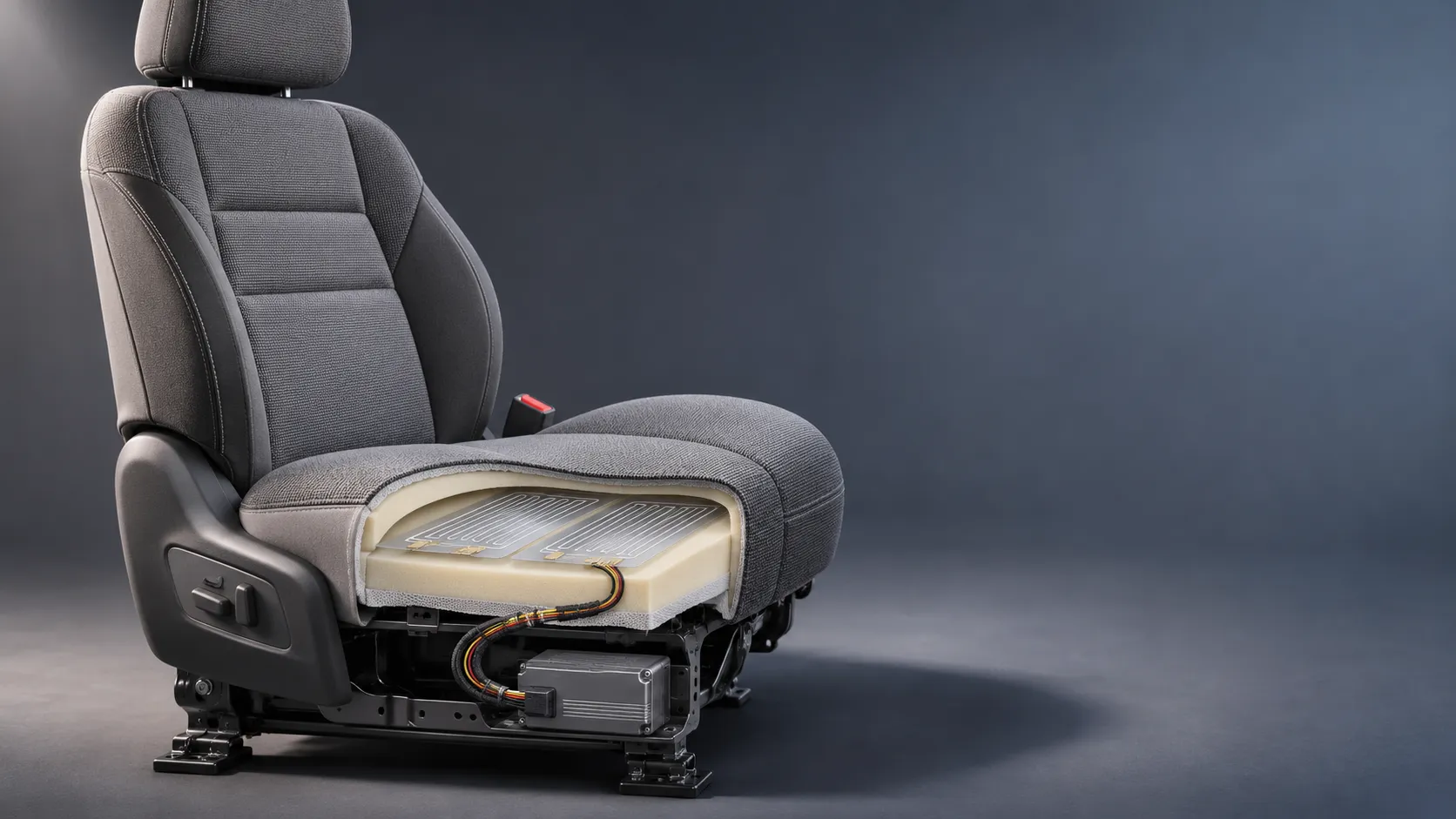
How Capacitive Seat Occupancy Sensing Works in Automotive Airbag Systems
Discover how capacitive seat occupancy sensing supports automotive airbag systems, and explore the design, calibration, and validation challenges behind reliable performance.
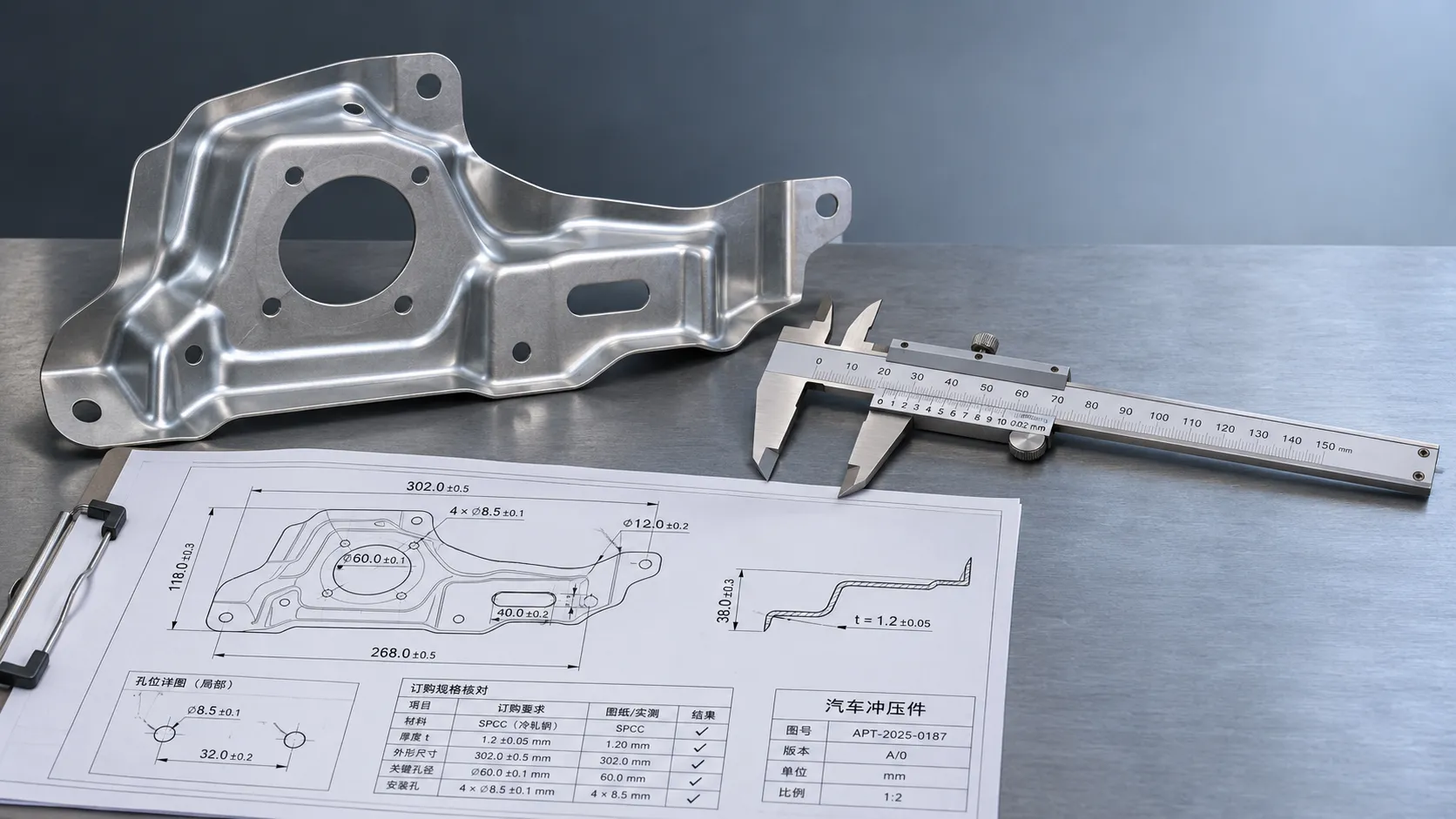
Industrial Product References: How to Verify Specs Before Ordering
Use an industrial product reference for procurement to verify specs, compatibility, and certifications before ordering—and reduce costly purchasing risks.
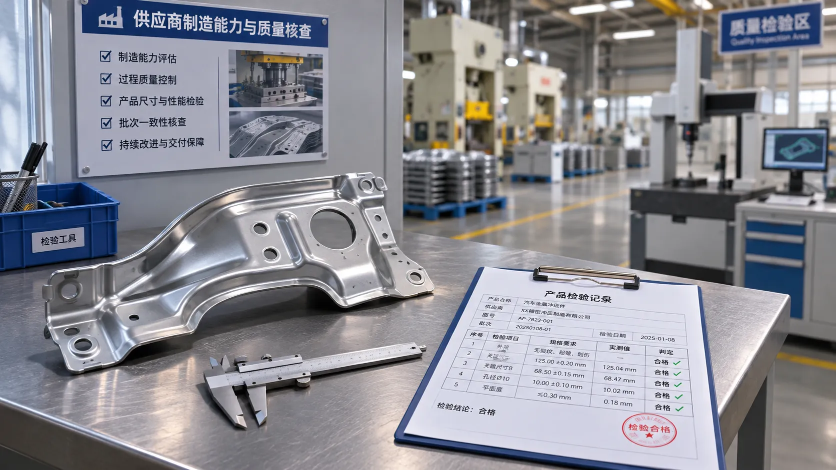
Choosing a Private Label Partner in Europe: Key Supplier Criteria
Private label cooperation Europe buyers can trust starts with the right supplier. Explore key criteria for compliance, quality, traceability and supply resilience.

Integrated Cabin Comfort Systems: How Seat and Cabin Climate Controls Work Together
Discover how integrated cabin comfort systems coordinate seat and climate controls to balance occupant comfort, energy use, safety, and performance.
Automotive Ergonomics Pricing: What Drives Seat System Costs?
Discover what drives automotive ergonomics pricing, from seat mechanisms and safety systems to tooling and volume, and learn how to compare supplier quotes.
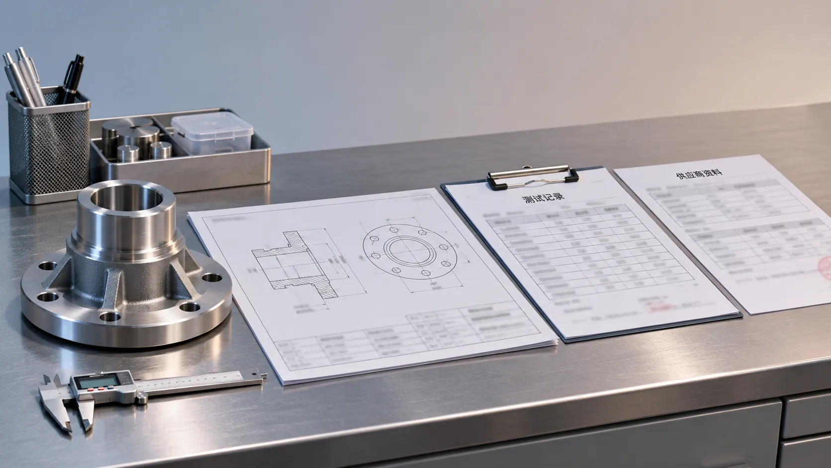
Evaluating Supplier Solutions: How to Verify References and Standards
Supplier solution references and standards can make or break a sourcing decision. Learn how to verify claims, assess compliance, and reduce risk before awarding a contract.
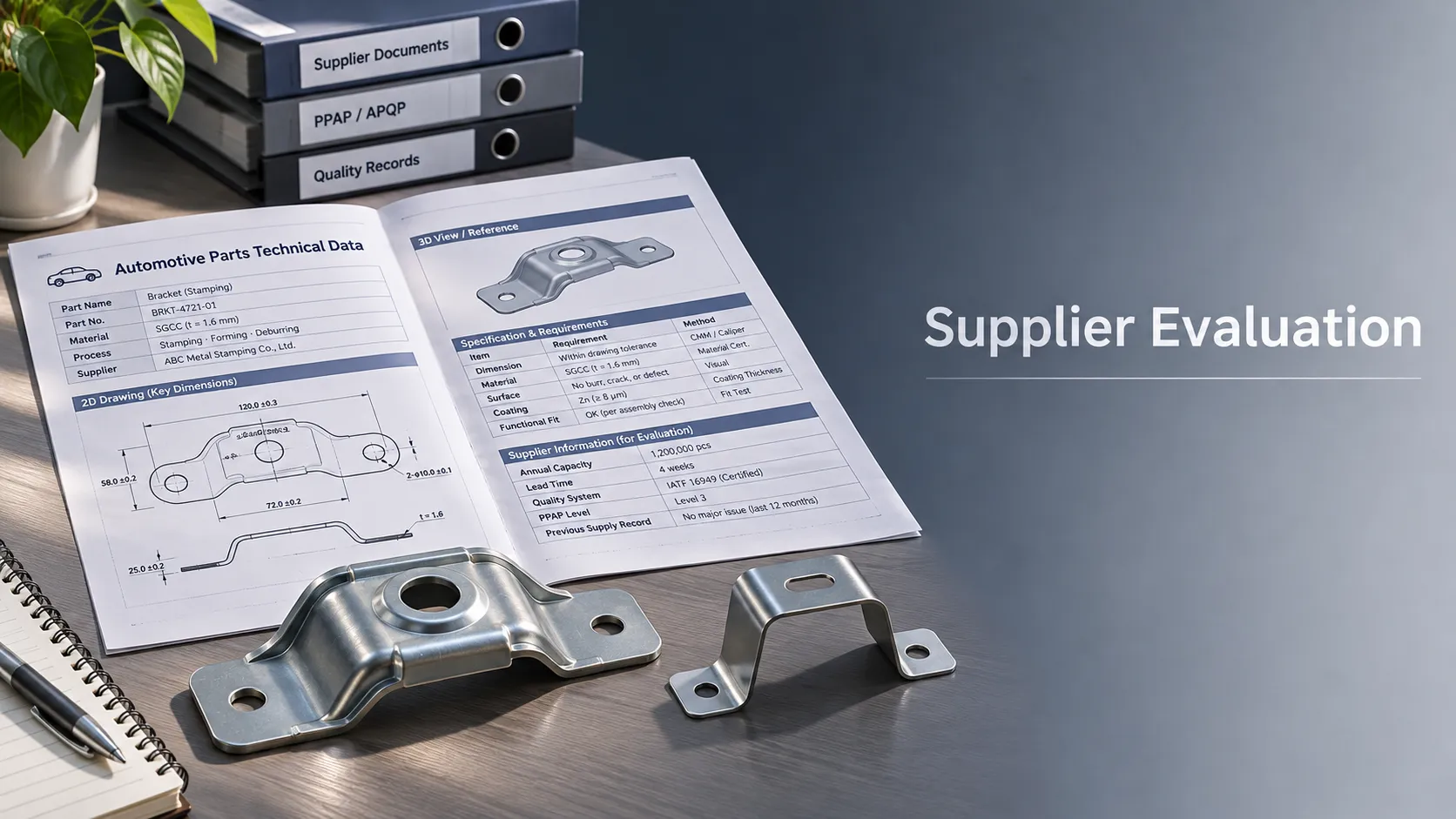
Choosing B2B Product Knowledge Platform Suppliers: Key Evaluation Criteria
Compare B2B product knowledge platform suppliers with confidence. Explore key criteria for data accuracy, supplier transparency, integrations, and value.

Choosing a Marine Radar Systems Supplier: What to Check Before Buying
Choosing a marine radar systems supplier? Compare installed costs, bridge compatibility, compliance evidence, and service support before you buy.
Related News
- 00
0000-00
How to Specify High-Strength Body Components for Crash Loads and Lightweighting - 00
0000-00
How EV battery collision impact protection limits pack deformation - 00
0000-00
Selecting High-Strength Lightweight Materials for Safer, More Efficient Vehicles - 00
0000-00
How to Evaluate High Strength Hot Stamped Steel Parts for Crash-Safety Applications - 00
0000-00
How to Evaluate Steel Auto Body Stampings for Strength, Fit, and Cost
0000-00
Weekly Insights
Stay ahead with our curated technology reports delivered every Monday.