
How EV battery collision impact protection limits pack deformation
EV battery collision impact protection limits pack deformation by controlling where crash energy enters the vehicle, how it is redirected, and how much residual intrusion reaches the battery enclosure. The battery pack does not need to remain visually perfect after a severe event. It must, however, retain sufficient clearance around cells, electrical connections, cooling components, and the enclosure seal so that deformation does not escalate into internal short circuit, coolant loss, electrical exposure, or delayed thermal propagation.
The practical limit is therefore not a single enclosure strength value. It is a system boundary defined by the crash pulse, vehicle load paths, pack position, mounting behavior, underbody geometry, enclosure stiffness, cell compression tolerance, and the condition of joints after impact. A pack that withstands a vertical underbody strike may react very differently to a narrow side-pole load, even when the nominal impact energy appears similar.
Deformation must be interpreted by location, mode, and timing
Measured intrusion alone can be misleading. A shallow local dent in a lower cover can be acceptable when it remains outside the cell protection zone and does not buckle a cooling plate or disturb a seal. A smaller displacement near a module edge, high-voltage connector, or side rail interface can be more serious because the local geometry concentrates force into vulnerable components.
Three deformation modes deserve separate review:
- Global bending occurs when the full enclosure deflects between vehicle mounting points. It can alter module clearances over a broad area and load fasteners, brackets, and busbar interfaces at the same time.
- Local indentation is associated with a pole, curb, road debris, suspension component, or fractured body member. The contact footprint and the local stiffness transition around the strike point often matter more than total pack displacement.
- Progressive crushing develops when a side sill, cross member, or enclosure rail folds toward the modules. This mode is especially sensitive to whether the intended crush structure collapses before the battery case is engaged.
Timing matters as much as final shape. A short, high-rate load can create local cracking, fastener pull-through, or cell damage before a structure reaches its maximum recorded displacement. Conversely, a visibly bent enclosure may have absorbed energy gradually through controlled yielding without transferring an unacceptable load to the cells. Post-crash inspection must therefore relate the final deformation pattern to the expected load path rather than treating every dent as equivalent.
The load path determines whether the pack becomes a structural target
A battery enclosure is usually positioned inside a wider vehicle crash-management system. Front and rear structures are intended to decelerate the vehicle before longitudinal loads approach the pack. In a side impact, rocker reinforcements, pillars, floor cross members, and transverse beams are expected to spread a concentrated strike over a larger section of the body. The pack should receive managed support from these surrounding structures, not become the first rigid obstacle in the load path.
Problems arise where nominally continuous load paths are interrupted by geometry, joining, or assembly variation. A gap between a sill reinforcement and a pack-side rail can permit a body member to gain speed before contacting the enclosure. A stiff mounting bracket may bypass a sacrificial crush feature and inject load directly into the tray. A sealing flange extending beyond a protective rail may become the first point of contact, turning a sealing feature into a bending initiator.
The relationship between the enclosure and adjacent body parts must also account for tolerance stack-up. Clearances established in a computer model can shrink after stamping springback, adhesive bead variation, coating thickness, bracket distortion, or pack installation. A small reduction in the designed gap may remove the delay needed for an outer rail to crush before it reaches the battery case.
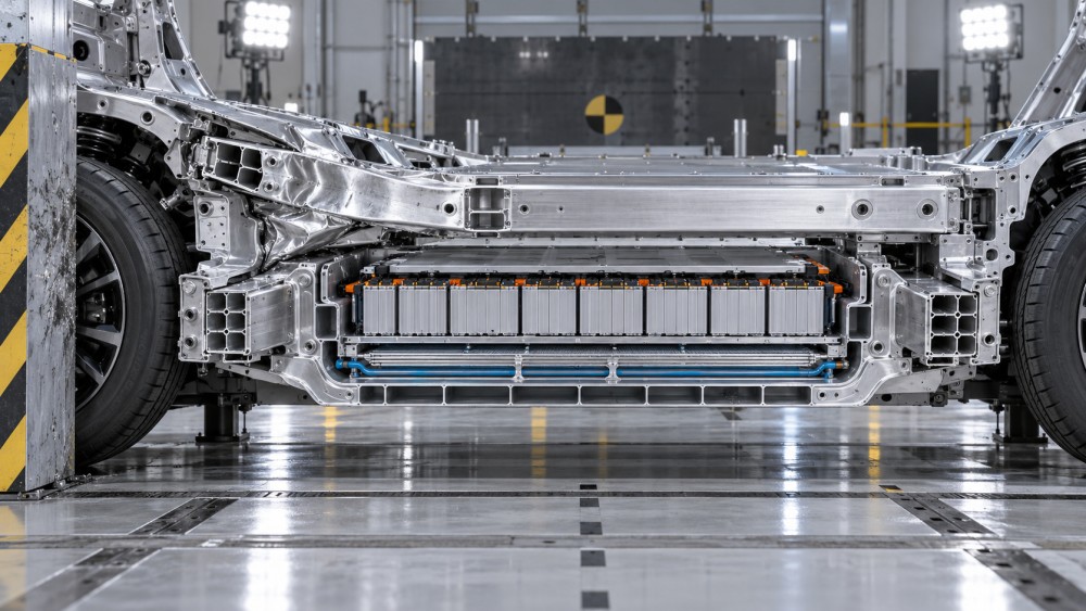
Energy absorption is useful only when collapse remains controlled
Side rails, crash cans, cross members, foam elements, and tailored blanks are commonly used to absorb energy before the cell region is threatened. Their value comes from stable progressive deformation. A component that is very stiff can limit early intrusion but transfer a sharp force peak into the enclosure. A component that is too compliant can collapse prematurely and leave insufficient residual space for the later stages of an impact.
Material selection cannot be separated from section geometry. High-strength steel can provide compact load-bearing rails, but its forming history, local thinning, weld access, and fracture behavior affect the useful deformation range. Aluminum extrusions can create multi-cell sections that fold efficiently, yet sharp corners, local buckling triggers, and heat-affected zones at joints need close control. Cast nodes may consolidate complex attachments, but they require careful transition design where a stiff node meets a more deformable extrusion or sheet structure.
For the pack itself, the lower tray and upper cover have different tasks. The lower structure often resists road strike, supports cooling hardware, and contributes to bending stiffness. The upper cover primarily protects against debris and prevents external access, while also maintaining enclosure sealing. Treating both panels as simple skins overlooks how their beads, flanges, ribs, and joints establish the box-section behavior of the complete pack.
A locally reinforced cover does not automatically improve collision performance. Reinforcement that ends abruptly can create a stiffness discontinuity, concentrating strain at the termination. Likewise, a thicker plate may reduce a dent at the contact point while increasing transmitted acceleration to modules beneath it. The preferable response depends on whether the dominant threat is puncture, broad bending, side intrusion, or bottoming against a rigid obstacle.
Cell protection clearance is a functional reserve, not empty space
The gap between the enclosure and the modules is often described as clearance, but it is an active deformation reserve. It accommodates enclosure deflection, manufacturing variation, thermal expansion, module swelling over service life, and movement at mounts. Once this reserve is consumed, further displacement can load module frames, cell stacks, cooling plates, or electrical joints.
Its required size cannot be judged from a single nominal drawing dimension. The relevant condition is the minimum residual clearance after combining build tolerances and impact deformation. A module with a robust frame may tolerate limited contact at selected edges, while a pouch-cell stack can be more sensitive to uneven compression. Prismatic and cylindrical cell architectures also distribute local loads differently through their supports and interconnects.
Cell-level compression limits should not be applied directly to pack-level intrusion. Between the outer case and an individual cell are rails, module housings, thermal interface materials, cooling elements, spacers, and fasteners. Each layer changes both force distribution and displacement. A pack can reach a concerning cell load before its enclosure shows major visible damage if a local internal support bridges the load. The opposite can also occur when a designed internal crush gap absorbs movement before the module is contacted.
Joints and mounting interfaces often set the real protection limit
Enclosure panels can have high nominal material strength while the assembly fails at a joint. Rivets, flow-drill screws, welds, adhesive bonds, bolts, and sealant joints respond differently under peel, shear, tension, and mixed loading. Collision deformation frequently changes a joint from its intended loading direction into a peel-dominated condition, where performance can decline sharply.
Bonded joints are particularly dependent on surface preparation, adhesive thickness, cure profile, overlap geometry, and environmental exposure. A bond line that performs well in a coupon shear test may not represent a long flange subjected to bending and edge peel. Mechanical fastening can provide retention after adhesive damage, but local hole deformation, insufficient edge distance, or galvanic protection details can alter the failure sequence.
Pack mounts deserve the same attention. They transfer road loads during normal use and crash loads during an event, often under opposing design objectives. A mount that is too rigid can transmit force into the tray before the surrounding vehicle structure dissipates it. A mount intended to release or deform must do so predictably; uncontrolled separation can shift the pack, damage high-voltage connections, or create new contact points with chassis members.
Protection performance changes with impact direction
Frontal and rear collisions typically challenge the integration between vehicle crash rails and pack end zones. The principal concern is progressive shortening of body structures until a cross member, drivetrain component, or suspension assembly approaches the enclosure. The critical review point is not simply whether the pack remains intact, but whether hard components have a credible path to bypass or contact it after upstream structures fold.
Side impact creates a more concentrated problem. The available lateral crush distance is limited, and the impact object may engage a narrow portion of the sill or door region. Strong side rails and internal cross members can spread the load, but their connection to the vehicle body determines whether they engage early enough. A rail placed close to modules can resist intrusion effectively yet leave little room for controlled collapse. A rail placed farther outward offers more crush distance but needs a reliable transfer path from the body side.
Underbody impacts differ again. Ground strikes introduce local contact geometry, abrasion, puncture risk, and repeated loading that may not resemble a single crash pulse. Protective shields should not be judged solely by thickness. Their attachment spacing, edge support, drainage features, trapped-debris risk, and clearance to cooling lines influence whether the shield distributes load or simply transfers a point impact into the tray.
Validation requires correlation between evidence layers
Simulation, component testing, full-vehicle testing, teardown inspection, and electrical assessment answer different questions. A finite-element model can identify likely folding and contact sequences, but confidence depends on material cards, joint representation, strain-rate behavior, boundary conditions, and realistic gaps. Simplifying a bonded-and-fastened flange into a fully rigid connection can conceal the mechanism that actually opens the enclosure.
Physical tests should capture more than peak acceleration and maximum intrusion. High-speed images reveal the order of contact. Load traces indicate whether a crush member worked progressively or produced an early spike. Post-test sectioning can distinguish outer-skin deformation from internal support contact. Electrical isolation, coolant containment, continuity of low-voltage sensing circuits, and inspection of vent paths complete the picture because an enclosure that appears structurally sound can still have lost essential protective functions.
Correlation failures are often traced to ordinary production details: a changed adhesive bead profile, local material thickness drift, a revised fastener, altered heat treatment, or a fixture that constrains a part differently from the vehicle. These are not minor variations when the design relies on a narrow clearance reserve or a precise buckling sequence.
Useful acceptance criteria go beyond visible damage
Post-impact evaluation should distinguish cosmetic deformation from loss of containment. The relevant questions are whether the enclosure remains closed, whether the high-voltage system retains required isolation and disconnection behavior, whether coolant and dielectric barriers remain intact, whether venting routes remain functional, and whether cell-bearing structures have been loaded beyond their intended limits. A dent may be repairable; a distorted joint that compromises sealing or shifts a module support requires a different disposition.
Traceability is equally important when comparing test articles and production parts. Material lot identity, forming condition, adhesive batch and cure record, fastener specification, torque or installation monitoring, and dimensional inspection data make it possible to determine whether an unexpected deformation reflects the design or the build. Without that evidence, repeated tests can produce visually different outcomes without explaining why.
Effective EV battery collision impact protection preserves a sequence: outer vehicle structures engage first, energy-absorbing features deform in a controlled manner, enclosure rails and panels distribute remaining load, and internal clearances prevent harmful transfer to the cells. Pack deformation becomes dangerous when that sequence is interrupted, bypassed, or consumed earlier than intended.
Related News

How to Evaluate Supplier Solution References Before Signing a Contract
Evaluate supplier solution references with confidence. Learn how to verify technical evidence, identify delivery risks, and close gaps before signing a contract.
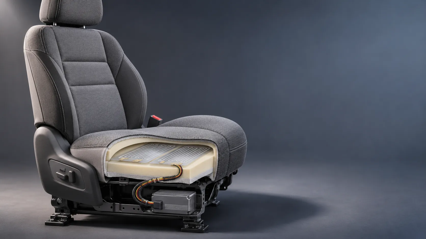
How Capacitive Seat Occupancy Sensing Works in Automotive Airbag Systems
Discover how capacitive seat occupancy sensing supports automotive airbag systems, and explore the design, calibration, and validation challenges behind reliable performance.
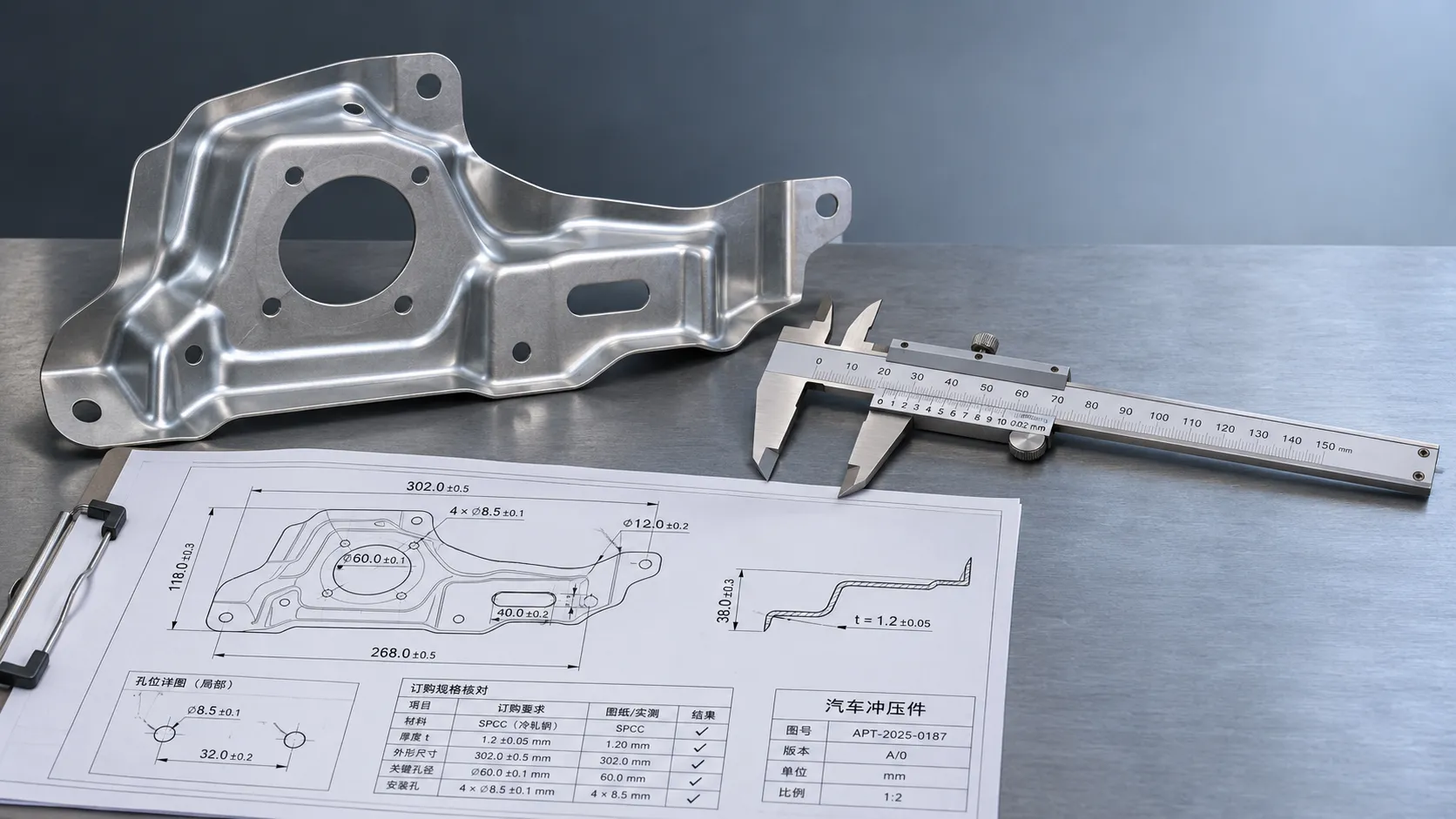
Industrial Product References: How to Verify Specs Before Ordering
Use an industrial product reference for procurement to verify specs, compatibility, and certifications before ordering—and reduce costly purchasing risks.
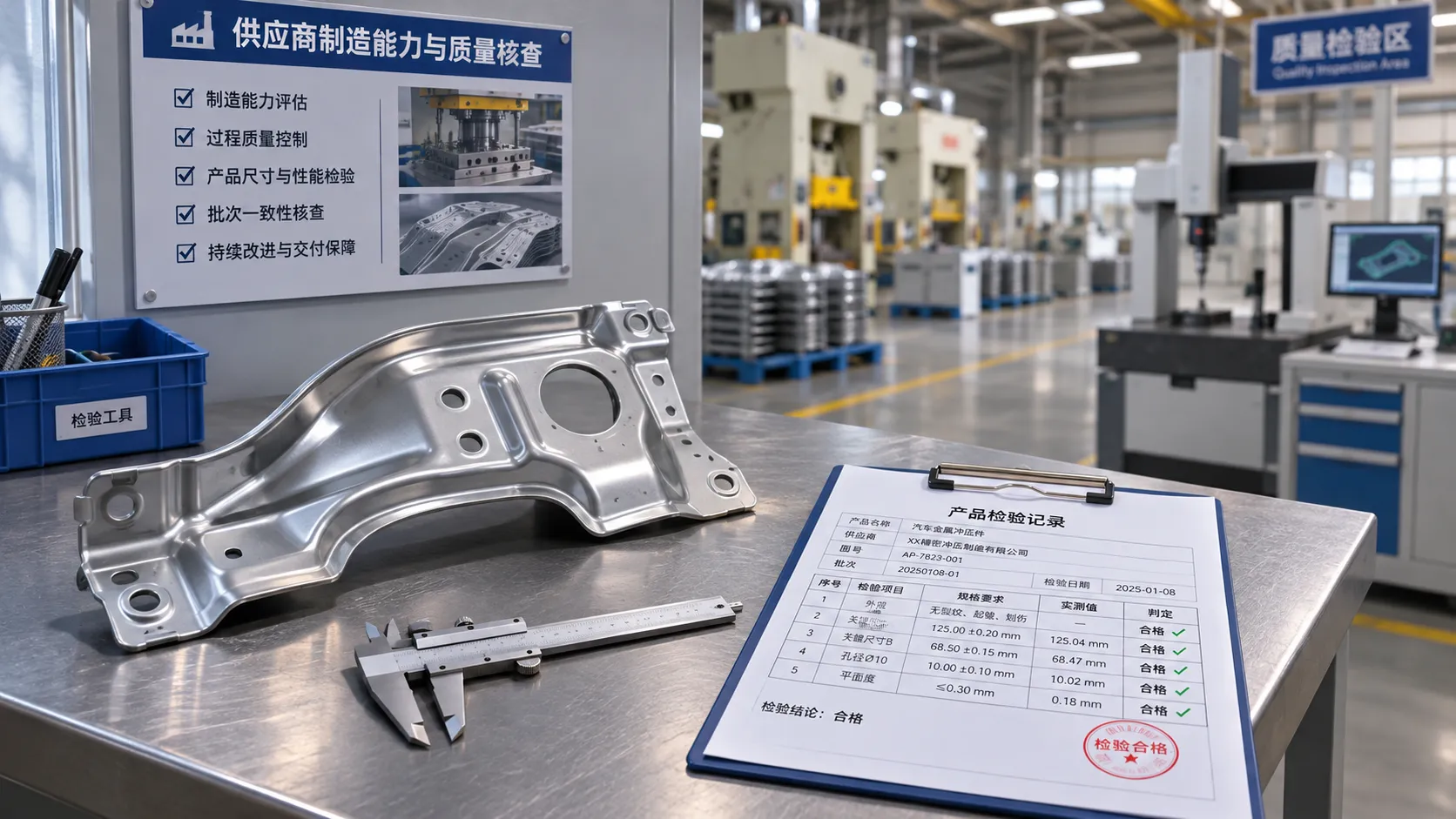
Choosing a Private Label Partner in Europe: Key Supplier Criteria
Private label cooperation Europe buyers can trust starts with the right supplier. Explore key criteria for compliance, quality, traceability and supply resilience.

Integrated Cabin Comfort Systems: How Seat and Cabin Climate Controls Work Together
Discover how integrated cabin comfort systems coordinate seat and climate controls to balance occupant comfort, energy use, safety, and performance.
Automotive Ergonomics Pricing: What Drives Seat System Costs?
Discover what drives automotive ergonomics pricing, from seat mechanisms and safety systems to tooling and volume, and learn how to compare supplier quotes.

Evaluating Supplier Solutions: How to Verify References and Standards
Supplier solution references and standards can make or break a sourcing decision. Learn how to verify claims, assess compliance, and reduce risk before awarding a contract.

Choosing B2B Product Knowledge Platform Suppliers: Key Evaluation Criteria
Compare B2B product knowledge platform suppliers with confidence. Explore key criteria for data accuracy, supplier transparency, integrations, and value.

Choosing a Marine Radar Systems Supplier: What to Check Before Buying
Choosing a marine radar systems supplier? Compare installed costs, bridge compatibility, compliance evidence, and service support before you buy.
Related News
- 00
0000-00
How to Specify High-Strength Body Components for Crash Loads and Lightweighting - 00
0000-00
How EV battery collision impact protection limits pack deformation - 00
0000-00
Selecting High-Strength Lightweight Materials for Safer, More Efficient Vehicles - 00
0000-00
How to Evaluate High Strength Hot Stamped Steel Parts for Crash-Safety Applications - 00
0000-00
How to Evaluate Steel Auto Body Stampings for Strength, Fit, and Cost
0000-00
Weekly Insights
Stay ahead with our curated technology reports delivered every Monday.