
How to Specify Integrated Marine Electronics for Reliable Bridge Operations
Start with the operating model, not the equipment list
A bridge retrofit or newbuild specification often begins with a list of familiar devices: radar, ECDIS, GNSS receiver, gyrocompass, AIS, echo sounder, VHF, autopilot, and bridge alarm systems. That list is necessary, but it does not define whether the bridge will operate reliably as one working environment.
For project managers, the practical question is whether integrated marine electronics will give officers coherent, trustworthy information during routine navigation, degraded-sensor conditions, port approaches, and emergency manoeuvres. A bridge can contain compliant individual products and still create operational risk if data is duplicated, delayed, inconsistently referenced, or difficult to interpret under pressure.
The specification should therefore begin with vessel operations. Define where the vessel trades, how often it enters confined waters, whether it uses pilots regularly, the expected watchkeeping model, available technical support, and the consequences of losing a particular function. A coastal workboat, offshore support vessel, ferry, container vessel, and polar-capable ship may all require broadly similar equipment categories, yet their integration priorities differ sharply.
For example, a vessel making frequent port calls may place more value on radar overlay alignment, pilot-friendly display access, conning data visibility, and rapid transition between sea and harbour modes. A vessel spending long periods offshore may give greater weight to redundancy management, alarm handling, remote diagnostics, and stable sensor performance across extended maintenance intervals.
Specify information flows before interfaces
Interoperability is often reduced to a simple question: “Can these products connect?” That is too low a threshold. A physical or digital connection does not establish that the receiving system understands the data correctly, updates it quickly enough, retains its integrity, or presents it in a usable form.
A useful specification describes critical data flows explicitly. Rather than stating that all bridge equipment must be integrated, identify the source, destination, update expectation, failure response, and preferred reference for each operationally important item.
This exercise exposes conflicts that a product catalogue cannot. Two position sources may agree in open water yet diverge near structures, under poor satellite geometry, or when a receiver is configured differently. A radar overlay can appear visually convincing even when heading alignment or sensor latency is wrong. AIS information may be useful for identification, but it should not be treated as an independent confirmation of radar detection in every circumstance.
Requirements should also distinguish between data needed for display and data used to influence control. Sharing heading information with an ECDIS display has different consequences from supplying it to an autopilot, track-control function, or dynamic positioning-related workflow. The more a data stream affects vessel movement, the clearer its accuracy, validation, fallback, and alarm requirements should be.
Protect the bridge from single-point failures disguised as integration
Integration reduces manual transcription and can improve situational awareness, but excessive centralisation can make a local fault affect multiple bridge functions. A specification that routes every sensor through one processor, network switch, power supply, or display platform may simplify installation drawings while concentrating operational risk.
The right degree of separation depends on the vessel and applicable rules, but the project team should map failures at a functional level. Ask what remains available if a navigation network segment fails, if the primary heading source becomes unreliable, if a main display is lost, or if an equipment software fault causes invalid data to propagate. The answer should be based on actual operating capability, not simply on whether a backup device is physically fitted.
Redundancy is only useful when crews can recognize the changeover, access the alternate source, and continue working without ambiguous information. A backup GNSS receiver located on a separate network may provide resilience. It becomes less useful if its selection logic is obscure, its position quality alarm is not visible at the conning position, or connected systems continue to show old data without a clear indication.
Specify failure behaviour for the functions that matter most:
- How does each display indicate lost, degraded, delayed, or substituted sensor data?
- Can the watchkeeper identify the active source for position, heading, speed, and depth without entering a maintenance menu?
- What happens to radar overlay, chart orientation, target vectors, route monitoring, and autopilot operation after a source change?
- Does loss of a non-essential device generate a manageable advisory, or does it create a distracting cascade of alarms?
- Which components have independent power paths, and how is loss of power announced?
This is where a bridge design moves beyond the idea of “backup equipment.” The objective is controlled degradation: the vessel should retain enough verified information and control capability for its crew to make safe decisions while faults are diagnosed.
Make alarm management an operational requirement
A bridge can be technically well integrated and still be hard to operate if alarms arrive without priority, context, or a clear path to action. Alarm overload is particularly damaging during pilotage, close-quarters situations, machinery disturbances, poor visibility, or heavy traffic. Adding more sensor inputs can increase this burden unless alarm design is considered early.
Project teams should request an alarm philosophy alongside the equipment architecture. It should establish which system owns the primary alert, where it is repeated, whether acknowledgement is local or centralized, and how duplicate alerts are suppressed or distinguished. Operators need enough information to identify the originating fault and its navigational effect, without losing time to screens full of secondary messages.
Configuration discipline matters as much as the display design. Safety contours, cross-track limits, look-ahead settings, shallow-water alarms, radar guard zones, and AIS filters should be aligned with the vessel’s operating procedures. They cannot simply be left at factory defaults or set once during commissioning. A configuration that is appropriate for deep-sea passage may be unsuitable in confined waters; a setting that generates continuous low-value alerts will eventually be ignored.
The specification should require documented configuration baselines, role-based access where practical, and a method for recording material changes. This prevents a common handover problem: the bridge works during acceptance trials, but no one can establish later why a threshold was chosen, who changed an interface setting, or whether a display mode has been altered since delivery.
Assess interfaces as a lifecycle commitment
Many integration problems emerge after delivery rather than during installation. A software update changes an output format. A replacement sensor does not reproduce the older device’s data behaviour. A vendor revises its network architecture. A new chart, communications, or cybersecurity requirement adds pressure to a bridge system that was designed around older assumptions.
For this reason, interface documentation is not an administrative attachment. It is a lifecycle asset. The owner or project authority should receive a controlled record of network topology, serial and Ethernet interfaces, message formats, port assignments, source priorities, software versions, licenses, alarm paths, and change procedures. It should be detailed enough for a qualified technician to diagnose a fault without reverse-engineering the bridge.
Open standards and widely supported protocols can reduce dependence on a single supplier, but they do not eliminate integration work. Implementations vary, optional fields may be handled differently, and proprietary functions may remain important for advanced features. A multi-vendor bridge can be an appropriate choice when it is supported by clear responsibility boundaries and tested interfaces. It becomes risky when each supplier accepts responsibility only for its own box.
Contracts should identify who is accountable for end-to-end functionality. That party does not need to manufacture every component, but it must coordinate interface design, commissioning evidence, defect resolution, and software compatibility across the bridge system. Without this assignment, problems involving sensor data, display behaviour, and network traffic can become prolonged disputes between vendors.
Test scenarios, not only components
Factory and harbour acceptance tests are essential, yet a checklist that confirms every device powers on and exchanges data will not prove bridge usability. Test plans should include operational scenarios that reveal integration weaknesses before handover.
Useful scenarios include loss of primary GNSS, invalid gyro data, radar target loss, AIS data interruption, network segment failure, loss of a principal display, power transfer, alarm acknowledgement from different locations, and changeover to backup equipment. For vessels using track control or closely linked autopilot functions, testing should also cover the intended operating boundaries, manual override, source selection, and the way alerts are presented to the officer of the watch.
Commissioning should involve the people who will operate and maintain the system, not only installers and equipment specialists. Officers can identify whether conning information is legible from normal working positions, whether screen transitions are intuitive, and whether alarm messages identify an actionable issue. Technical personnel can confirm that diagnostic access, spare-port strategy, grounding, cable labeling, and software recovery procedures are practical after the vessel enters service.
Acceptance criteria should state what evidence is required: interface test records, sensor alignment checks, alarm matrices, backup demonstrations, software inventories, configuration files, and crew familiarisation records. This creates a more durable handover than a generic completion certificate.
Use a phased specification process
For many projects, the most reliable route is to separate operational design from final equipment selection. In an early phase, define the bridge functions, critical data flows, operator stations, redundancy goals, and compliance obligations. In the next phase, evaluate proposed equipment architectures against those requirements, including third-party interfaces and lifecycle support. The final phase should lock down configuration, testing, documentation, training, and change control.
This sequencing prevents an expensive pattern: selecting a suite because its individual capabilities appear strong, then trying to resolve mismatched data paths and operator workflows during installation. It also gives project managers a firmer basis for comparing bids. Price can then be assessed alongside integration responsibility, test scope, documentation quality, supportability, and the operational consequences of failure.
Reliable bridge operations are built through disciplined decisions about information authority, degraded modes, alarms, and accountability. A well-specified integrated bridge does not merely place more data on screens. It helps the crew understand which information can be trusted, what has changed, and how to continue navigating when the system no longer behaves as planned.
Related News
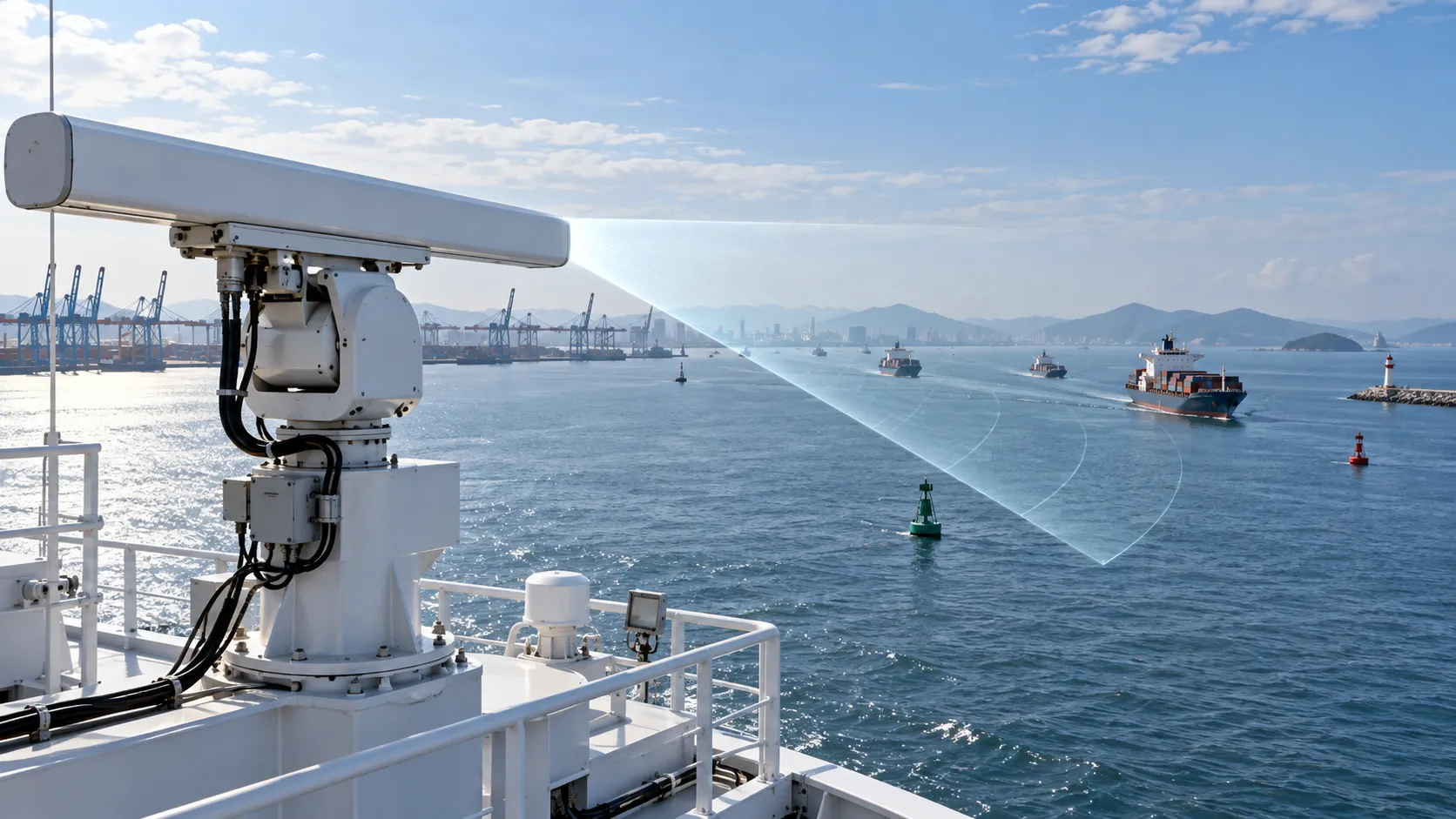
How to Evaluate Navigation Radar Manufacturers for Commercial Vessel Projects
Navigation radar manufacturers: learn how to compare performance, compliance, integration, support, and lifecycle cost for commercial vessel projects.

How Adjustable Cabin Ergonomics Reduce Operator Fatigue in Long-Shift Vehicles
Adjustable cabin ergonomics reduces operator fatigue through better seating, reach, visibility, vibration control, and climate comfort for safer long-shift vehicles.

How Rear-Impact Safety Components Work Together to Protect Vehicle Occupants
Explore how automotive safety components for rear impact work together—from crash structures and seats to head restraints and belts—to enhance occupant protection.
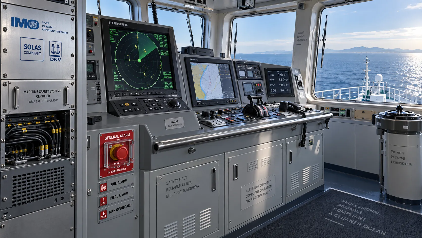
How to Evaluate a Marine Safety Systems Manufacturer for Vessel Compliance and Reliability
Marine safety systems manufacturer evaluation guide: verify compliance, engineering quality, lifecycle costs, and global service support for safer, reliable vessel operations.
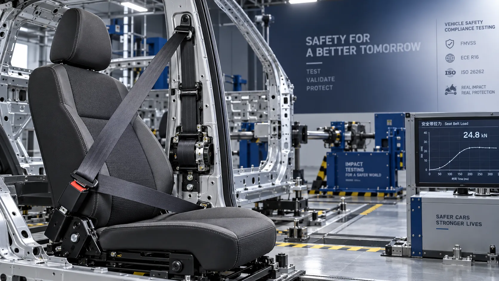
Crash Test Regulations for Seatbelts: Key Compliance Requirements Explained
Crash test regulations seatbelts explained: explore FMVSS, UN rules, anchorage strength, and dynamic restraint testing for safer, compliant vehicle systems.

How to Calculate the Total Cost of Automotive Lightweighting for a Vehicle Program
Automotive lightweight solutions cost: learn how to calculate program-level costs, including materials, tooling, joining, validation, risk, and vehicle-level value.

How Automotive Seat Occupancy Sensing Improves Airbag Deployment Decisions
Automotive seat occupancy sensing helps optimize airbag deployment decisions, improving passenger classification, safety diagnostics, and compliance across real-world conditions.

What Drives Lightweight Body Component Costs in High-Volume Vehicle Programs?
Lightweight body components cost depends on material yield, forming, joining, tooling, validation, and logistics. Explore proven ways to optimize total vehicle program cost.

How to Evaluate a Crash Safety Components Exporter for Global OEM Supply Programs
Choose a crash safety components exporter with proven certification, traceability, testing, and OEM launch support. Use this guide to reduce global supply risk.
Related News
- 00
0000-00
How to Specify Integrated Marine Electronics for Reliable Bridge Operations - 00
0000-00
How Adjustable Cabin Ergonomics Reduce Operator Fatigue in Long-Shift Vehicles - 00
0000-00
How to Evaluate a Marine Safety Systems Manufacturer for Vessel Compliance and Reliability - 00
0000-00
How to Calculate the Total Cost of Automotive Lightweighting for a Vehicle Program - 00
0000-00
What Drives Lightweight Body Component Costs in High-Volume Vehicle Programs?
Weekly Insights
Stay ahead with our curated technology reports delivered every Monday.