
How to Specify Body-Structure Safety Components for Crash Load Paths?
Start with the load path, not the part catalogue
A body-structure safety component should be specified as part of a controlled crash-load system. Selecting a stronger stamping, thicker reinforcement, or higher-grade steel in isolation can produce an expensive component that contributes little to occupant protection, or even shifts loads into an area that was never designed to carry them.
For technical evaluators, the first decision is whether the component is intended to preserve survival space, absorb energy progressively, manage intrusion, retain a restraint-system mounting point, or transfer load between those functions. The answer determines the material behavior, geometry, joining method, tolerance requirements, and validation evidence that should appear in the specification.
This matters because automotive safety components for body structures operate as a chain. Front rails, crash boxes, bumper beams, A- and B-pillars, rocker reinforcements, cross-members, roof rails, floor structures, seat cross-members, and restraint anchorage reinforcements all influence where impact energy travels. A part may meet its own drawing requirements and still fail the vehicle-level objective if the interfaces around it deform, separate, buckle too early, or become excessively stiff.
Define the intended function before defining material grade
The most common specification error is to begin with tensile strength. Strength is relevant, but it is only one input. A crash-load component needs a defined deformation role.
In a frontal impact, the preferred behavior for a forward energy-management structure may be controlled axial collapse. In contrast, a dash reinforcement, lower A-pillar reinforcement, or rocker section may need to retain shape long enough to redirect load around the passenger compartment. A B-pillar reinforcement must often balance intrusion resistance with load transfer to the roof rail, floor, and rocker. A seatbelt anchorage reinforcement has another duty: it must maintain the geometry and integrity of the restraint load path while the surrounding body deforms.
These functions lead to different component requirements:
- Progressive energy absorbers need predictable folding, stable crush force, controlled trigger features, and sufficient deformation stroke.
- Intrusion-resisting members need resistance to bending, local buckling, tearing, and joint separation under complex loading.
- Load-transfer members need compatible stiffness at their entry and exit points, because abrupt stiffness changes can create stress concentrations or bypass intended rails.
- Restraint-supporting structures need local strength, controlled displacement, reliable fastener retention, and a body attachment design that remains credible under dynamic occupant loading.
A useful requirement statement therefore describes the component's role in a load path before it names the proposed material. For example, a specification can require a reinforcement to maintain a prescribed force-transfer route between upper and lower body structures while limiting local collapse at its joints. That statement gives simulation, manufacturing, and test teams a common target. “Use ultra-high-strength steel” does not.
Assess the full structural route, including the interfaces
Crash loads do not respect organizational boundaries between stamped parts, body-in-white engineering, seat engineering, and restraint systems. The structural route must be assessed from the initial contact zone through the passenger-cell boundary and into the restraint attachment areas that control occupant motion.
For each proposed component, evaluators should map four points: where load enters, where it is expected to leave, what deformation is allowed within the part, and which adjacent parts must remain intact for the intended function to work. This map is especially important at rail-to-dash, pillar-to-rocker, roof-rail-to-pillar, and seat-to-floor interfaces. Those are locations where a locally robust component can lose value because the surrounding joints or thinner-gauge panels become the failure point.
Part-level stiffness targets should be treated cautiously. Higher stiffness can reduce intrusion in one mode while increasing peak deceleration, moving load toward the occupant compartment, or causing an unfavorable interaction in an offset or oblique impact. A reinforcement that performs well in a simple axial analysis may rotate under a real vehicle load case and place its weld flange in peel. The resulting separation can occur well before the base material reaches its nominal strength.
Evaluate load paths across more than one crash direction. A body-side reinforcement may be asked to contribute in side impact, pole impact, roof loading, small-overlap frontal impact, rear impact, and restraint loading. It does not need to carry the same function in each event, but the specification should identify the relevant modes and prevent a design optimized for one condition from damaging performance in another.
Specify material behavior over the manufacturing and crash life
Material selection should account for how the part behaves after forming, joining, coating, curing, and vehicle assembly. Nominal coupon properties are not enough for a component that has been hot stamped, roll formed, hydroformed, pierced, trimmed, welded, bonded, or exposed to thermal cycles.
High-strength and ultra-high-strength steels can provide efficient intrusion resistance, particularly where package space limits section size. Their use, however, raises questions about local ductility, hole-edge behavior, bend radii, joining sensitivity, and fracture prediction. A component may achieve excellent static strength while showing limited tolerance for trimming variation, local thinning, or a joint geometry that introduces edge loading.
Aluminum structures require a similarly specific assessment. Their crash response depends heavily on alloy condition, extrusion or stamping geometry, local buckling behavior, and the effect of joining processes on surrounding material. Mixed-material construction can reduce mass and improve packaging freedom, but it introduces galvanic-corrosion controls, differential thermal expansion, repair constraints, and a greater reliance on adhesives or mechanical fastening systems. A mass-saving claim has little decision value unless those integration conditions are included.
The specification should distinguish between a material requirement and a component performance requirement. Material requirements may include grade, thickness range, coating condition, forming limits, and approved supply route. Component requirements should address section geometry, dimensional stability, local thickness after forming, critical radii, flange condition, hole quality, and the crash-relevant force-displacement response. The latter is what protects against a nominally compliant material producing an inconsistent structural result.
For hot-stamped components, pay particular attention to property transitions where tailored tempering, partial reinforcement, or local heat effects are used. These zones can be intentional and beneficial, but they must be located and controlled with the load path in mind. An uncontrolled transition near a joint, mounting hole, or bend can create a fracture-sensitive region precisely where load concentration is highest.
Joining strategy is a crash requirement
Joining cannot be treated as a downstream manufacturing detail. In a crash event, welds, adhesives, rivets, clinches, bolts, and hybrid joints determine whether the load path stays continuous. Their placement and sequence can be more influential than a modest increase in base-material strength.
Technical specifications should define the joint function at each critical interface. A joint that is expected to transfer shear throughout an impact should not be assessed using only a coupon test that does not represent the surrounding panel stiffness. A flange that sees peel because of member rotation requires different evidence from a joint loaded mainly in lap shear. Adhesive bonds need consideration of bond-line thickness, surface preparation, curing window, environmental durability, and the behavior of the adjoining mechanical fasteners if the adhesive contribution degrades.
Joint access also matters. Some body structures can be designed around an ideal weld pattern that cannot be consistently achieved in production because of electrode access, stack-up variation, coating condition, or cycle-time limits. A robust specification identifies critical joints, states the required process controls, and includes an inspection approach proportionate to the consequence of failure.
When several material families are present, the joining specification should include corrosion management and repair assumptions. A structure that meets initial crash targets but cannot retain joint quality over its intended service environment has not met its safety purpose. Likewise, a collision repair method that replaces a high-strength reinforcement with a locally heated or improperly joined substitute can alter the load path for a subsequent crash. Repairability does not always govern the original design, but it should be considered where the component is likely to be damaged in low- to moderate-severity collisions.
Connect body performance to belts, seats, and airbags
Occupant protection is the final measure of a body structure's effectiveness. The body does not protect occupants merely by staying intact; it must create the timing and space in which seatbelts, airbags, and seats can manage human motion as intended.
Seat tracks, seat cross-members, belt anchorages, buckle mounts, and upper belt anchorage structures deserve particular scrutiny. Their load cases include occupant inertia transmitted through the restraint system, not just external crash loading. Local floor deformation may change seat position or belt geometry. Pillar deformation may alter the upper anchorage position. A seat frame can remain attached while its mounting area deforms enough to compromise the kinematics assumed by restraint calibration.
For this reason, a body component evaluation should include the interfaces that influence restraint geometry. Ask whether the proposed structure affects steering-column movement, pedal intrusion, seat travel, belt anchorage displacement, curtain-airbag deployment space, or side-airbag interaction. The appropriate answer may be “no material effect,” but it should be demonstrated rather than assumed from a body-in-white simulation alone.
Airbag systems can mask a structural weakness in an occupant injury metric under one condition, while a structural improvement can change occupant timing enough to require restraint recalibration. Body, seat, belt, and airbag teams need common assumptions about crash pulse, compartment intrusion, seat position, occupant size range, and sensing logic. A component release based only on structural metrics may therefore be premature when it sits near a restraint-relevant load path.
Ask for evidence that matches the decision risk
The required validation package should be proportional to the component's role. A cosmetic bracket does not demand the same evidence as a rocker reinforcement, seatbelt anchorage support, or roof-rail joint. Yet a specification should not rely on a single full-vehicle test result either. Vehicle tests are essential, but they can conceal whether performance comes from the intended component behavior or from compensating effects elsewhere in the structure.
A stronger approval case normally combines several forms of evidence:
- Material and formed-part characterization, including properties at critical formed or thermally affected locations.
- Component and joint tests that represent likely loading directions, fixture stiffness, and failure modes.
- Correlation between simulation and physical tests at the component or subsystem level before relying on vehicle-level prediction.
- Vehicle assessments covering the crash modes that govern the stated load-path function.
- Manufacturing capability evidence for critical dimensions, joining conditions, and traceability of safety-relevant material.
- Change-control rules for tooling adjustments, material-source changes, coating changes, welding parameters, adhesive systems, and local geometry revisions.
The last point is often under-specified. Crash performance can be sensitive to changes that appear minor in ordinary quality documentation: a revised trim operation, altered blank coating, shifted weld location, a new adhesive cure profile, or a different material batch route. Components serving a primary load path should have a defined escalation process for such changes, including criteria for renewed analysis or physical validation.
A practical specification sequence
Before issuing a sourcing package or approving a design release, start by documenting the vehicle-level crash objective and the component's intended role within it. Then define the allowable deformation mode, the critical interfaces, and the restraint-system dependencies. Only after those elements are clear should the team freeze material grade, thickness, forming route, and joint architecture.
The strongest specifications leave room for suppliers to improve manufacturability while keeping the safety function non-negotiable. They state the required structural behavior, identify controlled characteristics, and require evidence tied to credible failure modes. They do not confuse a high nominal strength value, a familiar manufacturing process, or a favorable single test with a complete crash-load-path solution.
That discipline is what turns body-structure safety components from individual parts into a dependable occupant-protection system.
Related News

How to Evaluate Supplier Solution References Before Signing a Contract
Evaluate supplier solution references with confidence. Learn how to verify technical evidence, identify delivery risks, and close gaps before signing a contract.
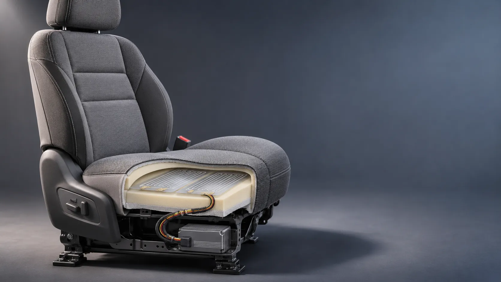
How Capacitive Seat Occupancy Sensing Works in Automotive Airbag Systems
Discover how capacitive seat occupancy sensing supports automotive airbag systems, and explore the design, calibration, and validation challenges behind reliable performance.
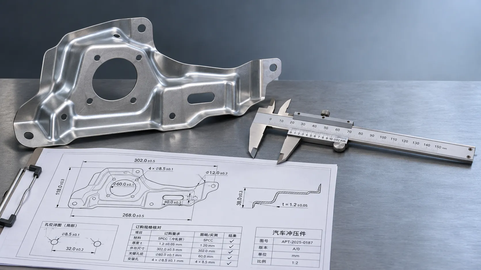
Industrial Product References: How to Verify Specs Before Ordering
Use an industrial product reference for procurement to verify specs, compatibility, and certifications before ordering—and reduce costly purchasing risks.
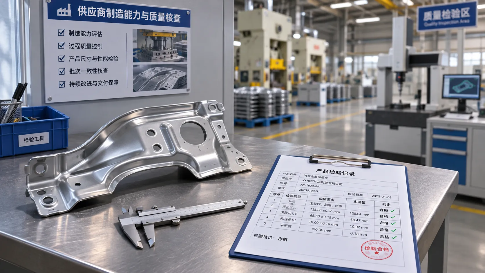
Choosing a Private Label Partner in Europe: Key Supplier Criteria
Private label cooperation Europe buyers can trust starts with the right supplier. Explore key criteria for compliance, quality, traceability and supply resilience.

Integrated Cabin Comfort Systems: How Seat and Cabin Climate Controls Work Together
Discover how integrated cabin comfort systems coordinate seat and climate controls to balance occupant comfort, energy use, safety, and performance.
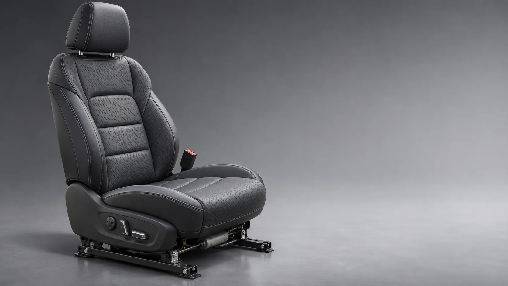
Automotive Ergonomics Pricing: What Drives Seat System Costs?
Discover what drives automotive ergonomics pricing, from seat mechanisms and safety systems to tooling and volume, and learn how to compare supplier quotes.

Evaluating Supplier Solutions: How to Verify References and Standards
Supplier solution references and standards can make or break a sourcing decision. Learn how to verify claims, assess compliance, and reduce risk before awarding a contract.

Choosing B2B Product Knowledge Platform Suppliers: Key Evaluation Criteria
Compare B2B product knowledge platform suppliers with confidence. Explore key criteria for data accuracy, supplier transparency, integrations, and value.

Choosing a Marine Radar Systems Supplier: What to Check Before Buying
Choosing a marine radar systems supplier? Compare installed costs, bridge compatibility, compliance evidence, and service support before you buy.
Related News
- 00
0000-00
How to Specify Body-Structure Safety Components for Crash Load Paths? - 00
0000-00
How 22MnB5 Hot Stamping Balances Crash Strength and Formability in Body Parts - 00
0000-00
22MnB5 Hot Stamped Steel Parts: Key Properties, Forming Limits, and Typical Uses - 00
0000-00
How to Evaluate Hot Stamped Steel Parts for Crash Performance and Weight Targets - 00
0000-00
Hot Stamping Processes Explained: Materials, Forming Steps, and Common Quality Defects
0000-00
Weekly Insights
Stay ahead with our curated technology reports delivered every Monday.