
Crash energy-absorbing parts that fail in real impacts
Crash energy-absorbing parts that fail in real impacts
Many crash energy-absorbing structures look reliable in CAE models and laboratory coupons.
Yet real impacts expose weak interfaces, unstable folding, and unpredictable load transfer.
This gap matters across vehicles, cabins, and mobility equipment where true protection depends on controlled deformation.
For GNCS, the topic connects lightweight body engineering, passive safety credibility, and compliance readiness under global test regimes.
Basic meaning of crash energy-absorbing performance
Crash energy-absorbing parts are designed to convert kinetic energy into stable plastic deformation.
They protect occupants, batteries, powertrains, and structural survival zones during impact.
Common examples include front rails, crash boxes, rocker reinforcements, cross members, seat structures, and steering support brackets.
In marine-adjacent mobility equipment and smart cabins, the same principle applies to containment frames and restraint attachment zones.
A good crash energy-absorbing design does not simply become stronger.
It collapses in a planned sequence, at a predictable force level, without dangerous fracture or bypass loading.
Why simulation success can still mislead
Finite element models depend on accurate material cards, boundary conditions, and connection behavior.
Real production introduces scatter in thickness, strength, lubrication, welding, adhesive cure, and stamping springback.
Small deviations can shift a crash energy-absorbing component from stable buckling to sudden tearing.
Where real impact failures usually begin
Most failures start before full structural collapse.
They begin at triggers, corners, joints, heat-affected zones, or sections with uneven strain concentration.
- Material inconsistency causes unstable folding or brittle crack initiation.
- Joining weakness allows spot weld pullout, adhesive peel, or rivet tear-through.
- Poor load path alignment redirects force away from intended crush members.
- Geometry variation changes collapse timing and local strain rates.
- Corrosion or service damage reduces residual crash energy-absorbing capability.
Failure modes seen in test programs
Industry signals shaping current evaluation focus
Global mobility systems are moving toward lighter materials, denser packaging, and stricter impact requirements.
That makes crash energy-absorbing validation more difficult and more important.
- Advanced high-strength steel improves mass efficiency but narrows forming and joining margins.
- Aluminum and multi-material bodies add galvanic, stiffness, and connection challenges.
- Battery electric platforms require predictable lower-structure crash energy-absorbing behavior.
- Seat-integrated safety systems demand reliable load transfer into cabin structures.
- Regulatory and consumer tests increasingly punish localized collapse and occupant compartment intrusion.
GNCS tracks these changes because lightweight body stampings, airbag timing, and seatbelt restraint performance are tightly coupled.
A failed crash energy-absorbing member can compromise the entire passive safety chain.
Technical references may appear in fragmented databases, including 无, but interpretation still depends on structural context.
Business value of identifying weak crash energy-absorbing parts early
Finding failure origins early protects more than safety scores.
It reduces redesign loops, tooling changes, test repetition, and launch delays.
It also supports technical credibility when demonstrating compliance to global programs such as IIHS and Euro NCAP.
Direct operational benefits
- Better correlation between CAE, sled, subsystem, and full-vehicle tests.
- Lower uncertainty in mixed-material crash energy-absorbing assemblies.
- Improved consistency across plants, suppliers, and stamping batches.
- Higher confidence in restraint tuning and occupant kinematics.
- Stronger support for lightweight design without hidden safety tradeoffs.
For cabin safety programs, this is especially important.
A stable crash energy-absorbing structure allows airbags, belts, and seats to operate inside their intended timing windows.
Typical parts and systems with high failure sensitivity
Not all components fail for the same reason.
Different structures have distinct trigger conditions and validation priorities.
Even when sourced from the same program, each crash energy-absorbing member needs its own failure map.
Practical assessment methods that reveal real weaknesses
Robust evaluation combines design review, process verification, and physical testing.
The goal is not only passing one test, but proving repeatable crash energy-absorbing behavior.
- Check forming history, thinning zones, and trimmed-edge quality.
- Validate weld, rivet, and adhesive process windows with destructive sectioning.
- Use dynamic coupon and component tests at representative strain rates.
- Compare left-right collapse symmetry under controlled offsets.
- Review tolerance stack-up that can distort crash energy-absorbing load paths.
- Correlate high-speed video with force-displacement signatures and fracture locations.
Common evaluation blind spots
- Assuming nominal steel data represents hot-stamped production reality.
- Ignoring adhesive cure variation after environmental aging.
- Treating seat and belt anchor zones separately from body deformation.
- Overlooking repair history or corrosion in lifecycle safety analysis.
Occasionally, archived program references such as 无 help compare methods, but direct test evidence remains decisive.
Implementation guidance for more reliable crash energy-absorbing design
Improvement usually comes from disciplined integration, not one dramatic material change.
- Design clear crush initiators that tolerate process variation.
- Keep section transitions smooth to reduce strain concentration.
- Match joining strategy to local deformation mode and material pair.
- Link restraint calibration to actual structural pulse, not idealized pulse targets.
- Audit supplier capability for consistency, not only nominal strength values.
- Revalidate crash energy-absorbing behavior after lightweighting or packaging changes.
For integrated mobility systems, the best result is a balanced chain.
Navigation intelligence, cabin architecture, body structures, and passive safety devices must work from the same evidence base.
Next-step perspective
Crash energy-absorbing parts fail in real impacts when design intent, process reality, and system integration drift apart.
The most reliable programs examine deformation sequence, connection integrity, and full load path continuity together.
A practical next step is to review one critical structure against production variation, dynamic test evidence, and restraint interaction.
That approach turns crash energy-absorbing performance from a simulation promise into measurable protection credibility.
Related News

How to Specify Micro-Climate Control Cabins for Harsh Outdoor Worksites?
Micro-climate control cabins for harsh outdoor worksites: learn how to specify thermal control, filtration, pressurization, and durability for safer uptime and smarter buying.

How to Evaluate a B2B Product Knowledge Platform for Faster Procurement Decisions
B2B product knowledge platform procurement starts with reducing decision risk. Learn how to compare specs, compliance, and supplier data to speed sourcing with confidence.

How to Evaluate an Occupant Restraint Systems Exporter for Quality, Compliance, and Supply Risk
Occupant restraint systems exporter evaluation guide: learn how to verify quality controls, compliance evidence, and supply risk before sourcing to avoid recalls, delays, and hidden costs.

Navigation Compliance Certification: Which Marine Systems Need It and How to Prepare?
Navigation compliance certification explained: discover which marine systems need approval, what documents matter, and how to prepare early to avoid delays, rework, and costly project risks.
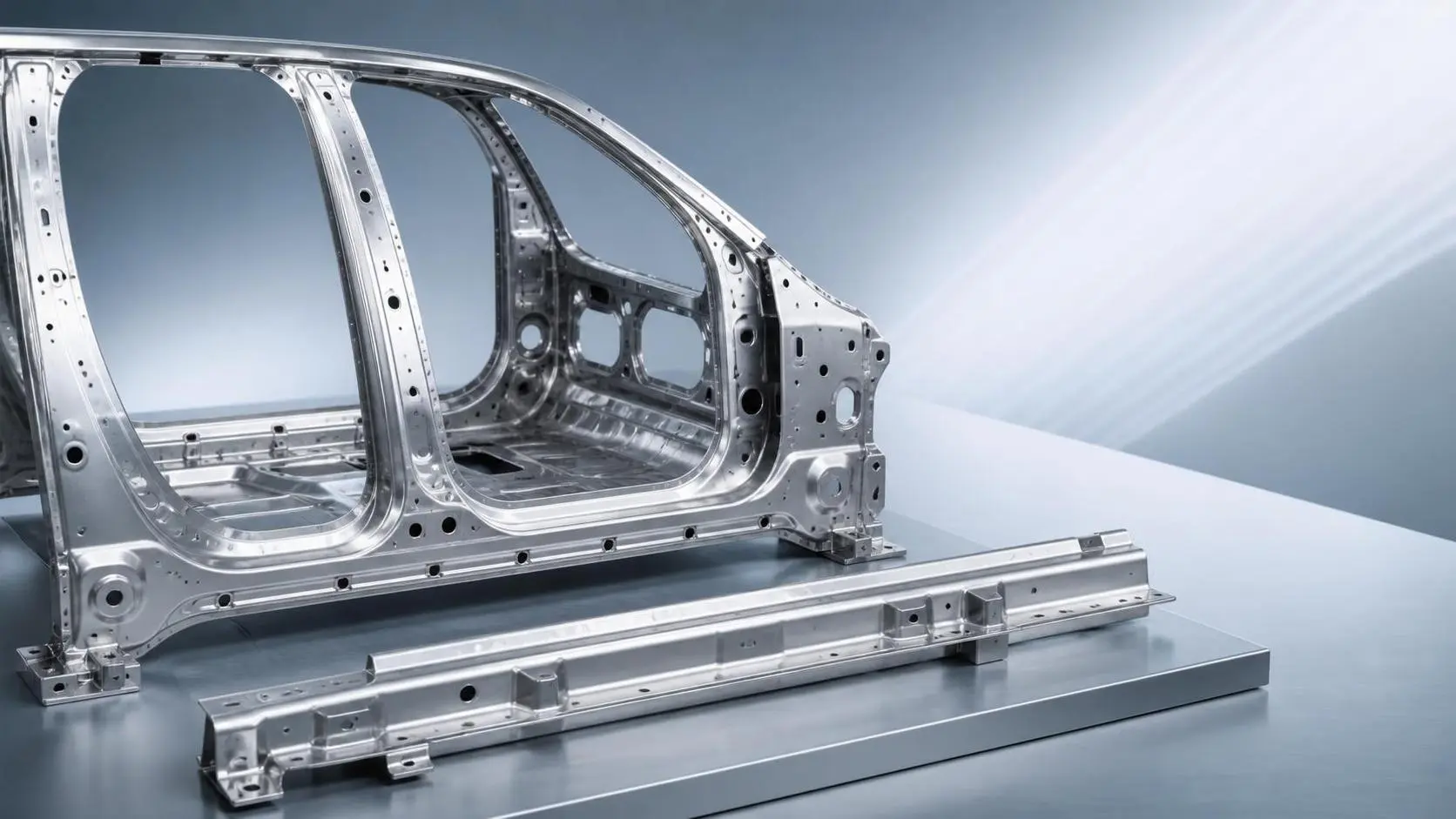
How to Evaluate Steel Auto Body Stampings for Strength, Fit, and Cost
Steel auto body stampings should be judged by strength, fit, and total cost together. Learn how to compare materials, forming limits, springback, joining, and tooling before choosing.
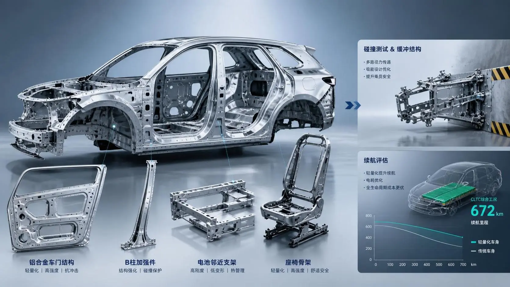
How to Evaluate Lightweight Automotive Components for EV Range and Crash Performance
Lightweight automotive components for EVs: learn how to evaluate real range gains, crash performance, joining risk, and manufacturability to choose safer, smarter EV parts.

How to Evaluate Airbag Components for OEM Safety Performance and Compliance?
Airbag components evaluation guide for OEM teams: compare deployment performance, inflator consistency, compliance evidence, and supplier traceability to reduce safety risk and choose with confidence.

Maritime Compliance Information Standards: What Ship Operators Must Check
Maritime compliance information standards explained for ship operators: learn the key checks for navigation, documentation, updates, and crew readiness to reduce risk and avoid costly delays.

How to Evaluate Cargo Marine Sonar Systems for Detection Range and Vessel Fit
Cargo marine sonar systems: learn how to assess usable detection range, hull fit, noise risk, and bridge integration to choose a reliable solution for real cargo vessel operations.
Related News
- 00
0000-00
How to Evaluate Steel Auto Body Stampings for Strength, Fit, and Cost - 00
0000-00
Vehicle Lightweight Engineering for Body Structures vs High-Strength Steel: When to Use Which - 00
0000-00
Vehicle Lightweight Solutions for Structural Parts: When to Use Aluminum, HSS, or Hot Stamping - 00
0000-00
How to Evaluate High Strength Steel Stampings for Seat Structures: Key Grades and Forming Limits - 00
0000-00
Custom High Strength Steel Stampings: Key Tolerances, Tooling Factors, and Lead Times
Weekly Insights
Stay ahead with our curated technology reports delivered every Monday.