
How to Build a Practical Solution Framework for Complex Engineering Projects
A practical solution framework starts by turning a broad engineering objective into a controlled set of decisions. “Improve navigation reliability,” “reduce crash intrusion,” or “increase seat comfort” are useful intentions, but they cannot guide design release, validation, or change control on their own. The framework must expose the physical behavior, operating conditions, interfaces, and evidence required before a team commits to a design path.
For complex projects, the first useful output is not a schedule. It is a decision model: a shared view of what must work, under which conditions, how failure is detected, and what evidence will prove the result. This prevents a familiar failure pattern in which electrical, mechanical, software, manufacturing, and compliance workstreams each optimize a valid local target while the assembled system behaves unpredictably.
Start with the operating boundary, not the feature list
Requirements often arrive as isolated statements: detection range, weight target, deployment timing, recline angle, corrosion resistance, installation space, or data update frequency. A solution framework connects those statements to the situation in which the product must perform.
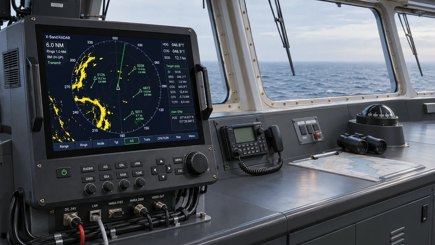
Take a marine navigation installation. Antenna placement, vessel structure, power quality, cable routing, nearby transmitters, weather exposure, and bridge display layout can all affect the usable result. A radar with strong laboratory performance may still produce operationally poor information when reflections from masts, cranes, or superstructure clutter the intended sector. Treating signal quality as a device-only specification leaves the installation boundary unmanaged.
The same principle applies to passive safety systems. An airbag module cannot be assessed only by inflator output or cushion volume. Restraint behavior depends on occupant position, seat geometry, seatbelt load path, trim breakaway behavior, sensor logic, vehicle deceleration pulse, and the time relationship between these events. A local component change can alter the sequence enough to invalidate assumptions made elsewhere.
Define the operating boundary with enough detail to distinguish normal use from the conditions that expose weak interfaces. Record the following early, in language that can be tested:
- Physical environment: temperature exposure, vibration, moisture, salt spray, dust, electromagnetic interference, and service access.
- Duty profile: continuous operation, intermittent activation, emergency operation, start-stop cycling, storage duration, and update frequency.
- Human interaction: sight lines, reach zones, maintenance actions, seating posture, restraint routing, alarm interpretation, and foreseeable misuse.
- System dependencies: incoming power, sensor accuracy, network latency, mounting stiffness, fastening method, software version, calibration state, and adjacent component tolerances.
This boundary should also state what is outside the current solution. Without that distinction, teams quietly absorb unresolved responsibilities. A seat frame team may assume the vehicle body provides a rigid attachment interface; the body team may expect the seat rails to accommodate variation. Neither assumption is harmless once load transfer, fastening access, or assembly sequence is considered.
Convert requirements into engineering claims
A requirement becomes actionable when it is written as a claim with a measurable condition and a verification route. “The system shall be durable” is not a claim that can be closed. “The display assembly shall retain readable contrast after the defined temperature, vibration, and illumination exposure” establishes a condition, an observable outcome, and a route to evidence.
Each significant requirement should be connected to four items: the controlled parameter, the acceptance condition, the verification method, and the owner of the evidence. This is more disciplined than assigning an owner to the requirement text alone. The person responsible for an airbag bracket geometry may not own the test fixture, the structural simulation, or the assembly torque record needed to demonstrate that the geometry performs as intended.
The distinction matters because an attractive isolated value may be irrelevant to the final behavior. High-strength steel can reduce gauge in a stamped reinforcement, yet the selected geometry may create forming sensitivity, springback variation, or a local joining problem. A lower-strength alternative with a more stable process window can be the stronger system choice if it produces repeatable geometry and predictable load transfer.
Build the architecture around interfaces that can fail
Most late rework originates at interfaces: hardware to software, module to structure, component to trim, sensor to control logic, or design intent to factory process. A framework should identify interfaces before detailed design is frozen and give each one explicit assumptions.
For every interface, define the exchanged quantity. It may be force, motion, current, data, heat, pressure, tolerance, retention load, visibility, or access. Then define the range, direction, timing, allowable variation, and failure response. “Seat sensor connects to controller” is too vague. A usable interface definition identifies connector retention, pin assignment, power state, communication behavior, diagnostic response, harness bend radius, routing protection, and conditions under which the controller treats a missing or implausible signal as a fault.
Separate coupling from coincidence
Two events occurring together do not always share the same cause. If a navigation display intermittently loses position data during heavy machinery operation, the cause may be power transients, grounding, cable shielding, network congestion, electromagnetic interference, or a software recovery defect. Replacing the receiver before isolating the failure mode can create a false sense of resolution.
Likewise, a seat squeak that appears after endurance cycling may arise from a loose fastener, trim-to-frame friction, rail contamination, weld distortion, foam movement, or a tolerance stack that changes under occupant load. The symptom is audible, but the engineering claim concerns relative movement at a particular interface. The investigation needs controlled replication, teardown observations, and comparison against a known-good build rather than a generic “noise reduction” action.
Use a compact interface register to capture these relationships. It should show the interface, the exchanged quantity, the design assumption, the validation method, and the escalation trigger. Keep it visible during design reviews. A large requirements database can preserve traceability, but it rarely makes an unstable interface obvious during a working discussion.
Choose validation evidence before selecting the final design
A framework becomes practical when verification is designed alongside the solution. This does not require every test to be fully specified at concept stage. It does require clarity on which decisions will rely on calculation, simulation, bench testing, vehicle or vessel integration testing, process capability evidence, inspection, or controlled analysis.
Validation methods are not interchangeable. Simulation is strong for comparing geometry changes, locating stress concentrations, and exploring load paths when material and boundary assumptions are sound. It is weaker when friction, joining variation, fracture initiation, sensor drift, deployment chemistry, or installation workmanship dominates the result. Bench tests isolate a subsystem but can hide assembly interactions. Full-system trials expose real interfaces but are expensive and can arrive too late to support economical redesign.
A balanced evidence plan places learning where it has the highest leverage. Early prototypes should target uncertainty, not merely demonstrate that a preferred concept can function once. If the critical unknown is whether a hot-stamped section retains dimensional stability after trimming and joining, a polished full vehicle prototype is less informative than representative coupons and assemblies made through the intended process route. If a concern involves radar blind sectors created by vessel geometry, a laboratory receiver test will not settle the installation question.
Define failure criteria before testing starts. Otherwise, teams can reinterpret ambiguous output after the fact. Criteria should include the performance threshold, the permitted degradation, the inspection method, and the disposition route for borderline results. A one-time pass is not always enough; repeatability across builds, environmental states, and software revisions may be the real release question.
Use risk controls that point to decisions
Risk registers often become lengthy inventories of generic concerns. Their value increases when each entry identifies a decision that would reduce uncertainty or contain impact. “Supplier delay” is a condition, not a useful control strategy. The relevant questions are whether the part has a single qualified source, whether the production tool is on the critical path, whether incoming variation can be detected before assembly, and whether an alternate process changes the approved performance envelope.
Technical risks need the same precision. For a restraint system, a risk statement such as “deployment performance concern” should be decomposed into timing, activation signal integrity, inflator storage condition, cushion unfolding path, module retention, trim opening, and interaction with the seatbelt. Each has different evidence and different containment actions.
Assign escalation triggers that are observable. Examples include a tolerance result outside the allocated stack, an unresolved diagnostic fault, a material lot with properties near a process limit, a failed environmental exposure, an interface assumption changed by another workstream, or a test result that passes only after an undocumented adjustment. The trigger should cause a specific review, not simply a status update.
Control change through consequences, not document traffic
Engineering projects change because requirements mature, packaging shifts, parts become unavailable, software evolves, or test findings reveal a missing condition. A change process fails when it asks only whether the drawing, bill of materials, or software identifier has been updated. The necessary question is what claims and interfaces are affected.
For each proposed change, trace the impact across function, safety behavior, environmental exposure, manufacturability, service procedure, verification evidence, and released configuration. Replacing a fastener material may appear minor, yet it can affect corrosion pairing, torque behavior, clamp load, tool access, assembly error proofing, and crash load retention. Moving a seat control module can solve harness routing while creating water exposure, thermal loading, or electromagnetic compatibility concerns.
Configuration control should identify the exact combination that was tested. A report tied only to a subsystem name has limited value if the result depends on a particular calibration, bracket revision, trim cut pattern, material grade, or installation position. Retaining this relationship avoids a common release error: applying evidence from a similar build to a materially different one.
Make cross-functional reviews evidence-led
Useful reviews are organized around unresolved claims, interface assumptions, test evidence, and release decisions. Status color alone does not reveal whether the work is converging. A green item with an untested boundary condition can be more dangerous than a red item with a clear corrective path.
Bring the relevant artifacts together: current requirement statements, interface definitions, drawings or models, process flow, test observations, open deviations, and the latest configuration record. The discussion should expose contradictions. A design may meet its packaging envelope while preventing a tool from reaching a critical fastener. A diagnostic strategy may identify a fault but not define whether the equipment enters a safe state. A seat assembly may meet static comfort targets while its wiring route fails after repeated recline movement.
Close each review with decisions that can be verified: approve an assumption, request a representative build, revise an interface limit, add a test condition, freeze a configuration, or stop release until a specified claim is demonstrated. This keeps the framework connected to engineering action rather than administrative reporting.
A robust solution framework does not eliminate uncertainty. It makes uncertainty visible, assigns it to the right technical boundary, and demands evidence before hidden assumptions become field problems. That discipline is what allows complex navigation, body, restraint, and cabin systems to move from concept into repeatable implementation without losing sight of the conditions that govern real performance.
Related News

How to Evaluate Supplier Solution References Before Signing a Contract
Evaluate supplier solution references with confidence. Learn how to verify technical evidence, identify delivery risks, and close gaps before signing a contract.
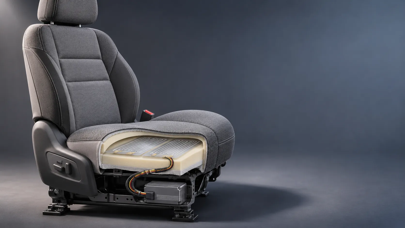
How Capacitive Seat Occupancy Sensing Works in Automotive Airbag Systems
Discover how capacitive seat occupancy sensing supports automotive airbag systems, and explore the design, calibration, and validation challenges behind reliable performance.
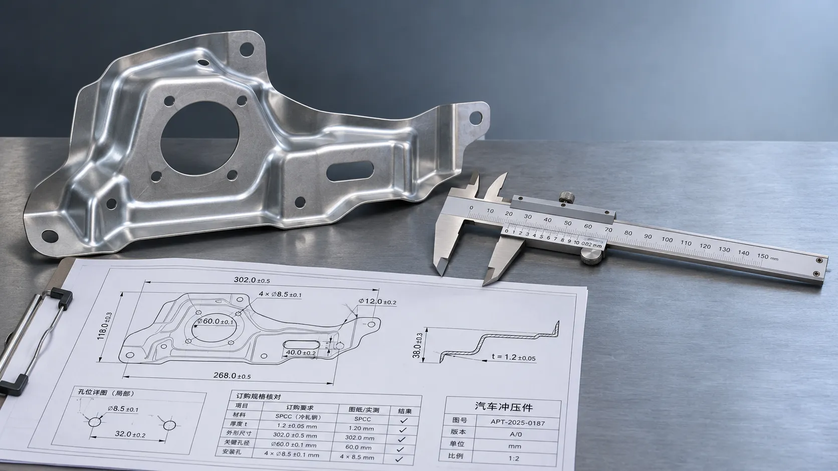
Industrial Product References: How to Verify Specs Before Ordering
Use an industrial product reference for procurement to verify specs, compatibility, and certifications before ordering—and reduce costly purchasing risks.

Choosing a Private Label Partner in Europe: Key Supplier Criteria
Private label cooperation Europe buyers can trust starts with the right supplier. Explore key criteria for compliance, quality, traceability and supply resilience.

Integrated Cabin Comfort Systems: How Seat and Cabin Climate Controls Work Together
Discover how integrated cabin comfort systems coordinate seat and climate controls to balance occupant comfort, energy use, safety, and performance.
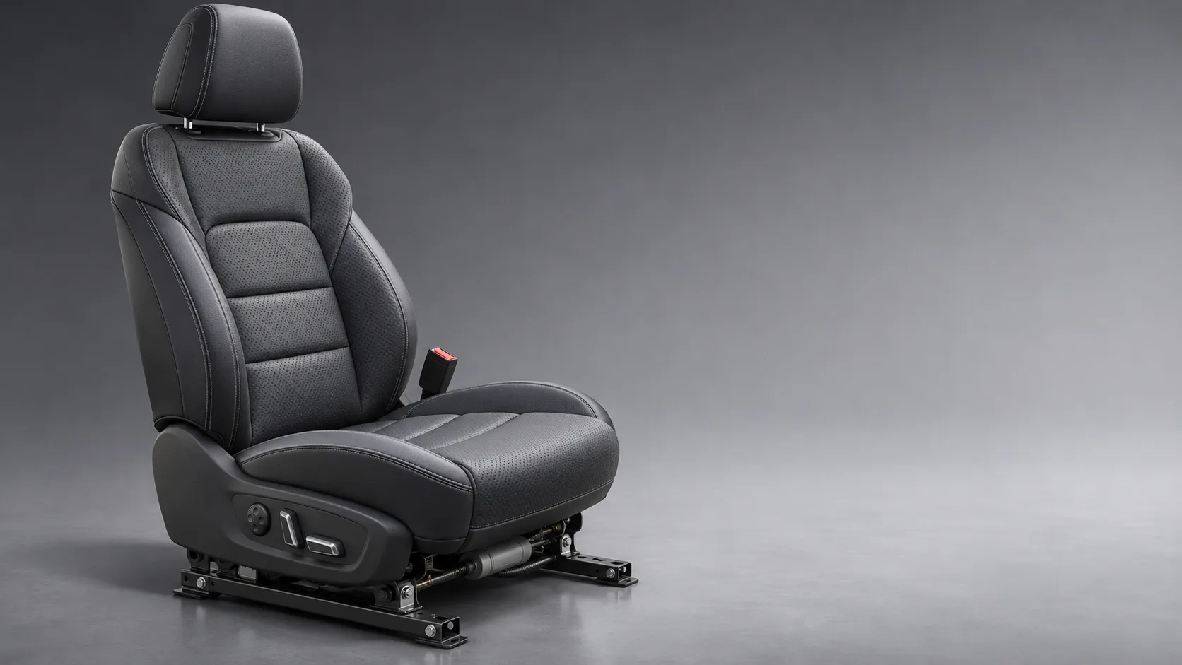
Automotive Ergonomics Pricing: What Drives Seat System Costs?
Discover what drives automotive ergonomics pricing, from seat mechanisms and safety systems to tooling and volume, and learn how to compare supplier quotes.

Evaluating Supplier Solutions: How to Verify References and Standards
Supplier solution references and standards can make or break a sourcing decision. Learn how to verify claims, assess compliance, and reduce risk before awarding a contract.
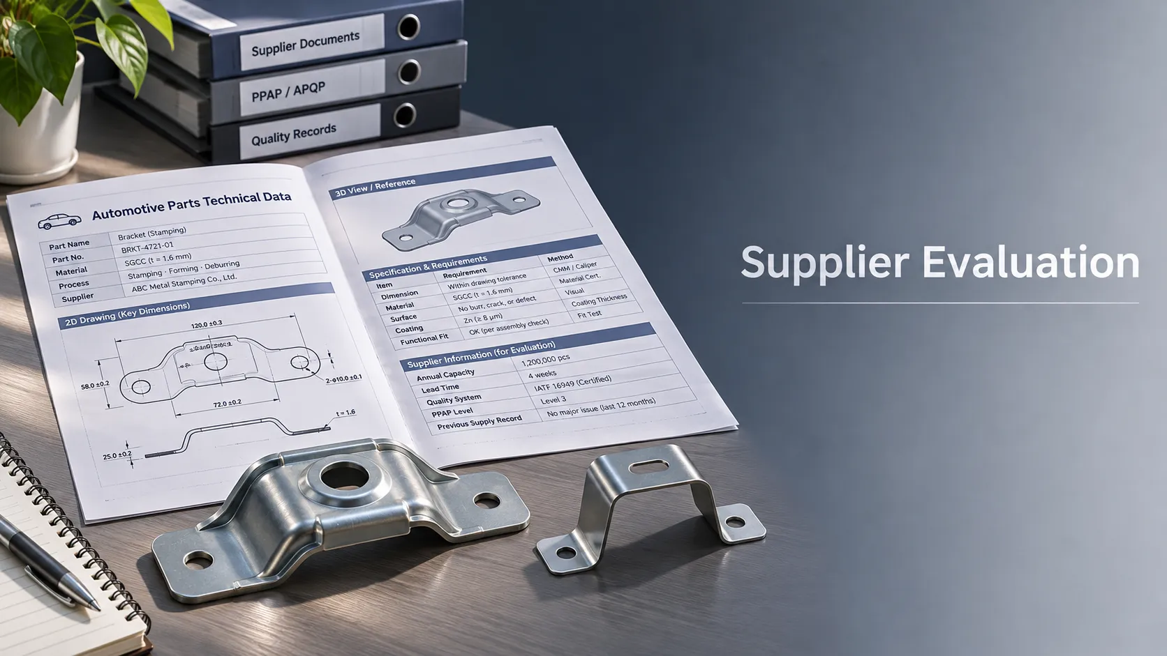
Choosing B2B Product Knowledge Platform Suppliers: Key Evaluation Criteria
Compare B2B product knowledge platform suppliers with confidence. Explore key criteria for data accuracy, supplier transparency, integrations, and value.
Choosing a Marine Radar Systems Supplier: What to Check Before Buying
Choosing a marine radar systems supplier? Compare installed costs, bridge compatibility, compliance evidence, and service support before you buy.
Related News
- 00
0000-00
How to Evaluate Supplier Solution References Before Signing a Contract - 00
0000-00
Industrial Product References: How to Verify Specs Before Ordering - 00
0000-00
Choosing a Private Label Partner in Europe: Key Supplier Criteria - 00
0000-00
Automotive Ergonomics Pricing: What Drives Seat System Costs? - 00
0000-00
Evaluating Supplier Solutions: How to Verify References and Standards
0000-00
Weekly Insights
Stay ahead with our curated technology reports delivered every Monday.